
Multistation energy-saving and low-noise dust removal system

A dust removal system and multi-station technology, applied in the direction of dust removal, dispersion particle separation, chemical instruments and methods, etc., can solve the problem of low utilization rate of air volume of multiple dust suction ports, high cost of replacement parts, high operating cost waste, etc. problem, to achieve the effect of solving low utilization rate, low operating cost and low energy consumption

Active Publication Date: 2015-04-01
HIMILE MECHANICAL SCI & TECH (SHANDONG) CO LTD
View PDF8 Cites 0 Cited by
  • Summary
  • Abstract
  • Description
  • Claims
  • Application Information

AI Technical Summary

Problems solved by technology

Therefore, a dust removal system must be installed in the workplace, but the dust removal system installed in some workplaces generally only uses a large dust suction port. Less dust is removed, and the same energy consumption is used when there are fewer people working and when there are more people working, resulting in waste of energy
[0003] If the existing dust removal system is multi-station dust removal, most of them use a high-power dust removal fan to drive multiple dust suction ports, which leads to the problem of whether the air volume of multiple dust suction ports is balanced and high operating efficiency caused by low utilization. The problem of cost waste, and the cost of replacement parts during maintenance is also high

Method used


Image

  • Multistation energy-saving and low-noise dust removal system
  • Multistation energy-saving and low-noise dust removal system
  • Multistation energy-saving and low-noise dust removal system

Examples

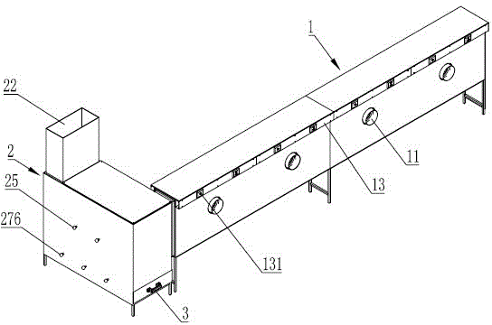
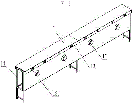
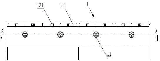

Embodiment Construction

[0026] Exemplary embodiments according to the present invention will be described in detail below with reference to the accompanying drawings. Here, it should be noted that, in the drawings, the same reference numerals are assigned to components having substantially the same structure and function, and redundant descriptions on components that are substantially the same are omitted in order to make the description more concise.

[0027] Such as figure 1 As shown, the multi-station energy-saving and low-noise dust removal system includes a dust collection box 1, and the dust collection box 1 is provided with a plurality of dust suction ports 11, such as image 3 and Figure 4 As shown, the dust suction port 11 is connected with a dust suction fan 12, and the dust suction fan 12 is connected with a dust suction control device, and the dust suction control device includes a controller connected to the dust suction fan 12, and the controller adopts The common fan controller belo...


PUM


Abstract

The invention discloses a multistation energy-saving and low-noise dust removal system, which comprises a dust collection box and a dust removal box, wherein a plurality of dust collection ports are formed in the dust collection box and communicated with a dust collection fan; the dust collection fan is connected with a dust collection control device; a dust outlet is formed in the dust collection box; a dust inlet communicated with the dust outlet is formed in the dust removal box; an air outlet is formed at one end of the dust removal box, which is away from the dust inlet; a dust filtration device is arranged in the dust removal box between the dust inlet and the dust outlet; a mechanical vibration device matched with the dust filtration device is arranged in the dust removal box; a dust accumulation device is arranged below the dust removal box; a plurality of dust falling ports communicated with the dust accumulation device is formed in the bottom wall of the dust removal box; and a dust falling sealing device is arranged corresponding to each dust falling port. Air with dust and smoke in a working place can be collected into the system and filtered by the dust filtration device, so that substances such as the dust can be retained in the dust removal box, and clean air can be discharged, thus protecting a worker from the harm of dust.

Description

technical field [0001] The invention relates to the field of dust removal equipment, in particular to a multi-station energy-saving and low-noise air dust removal system. Background technique [0002] At present, there are often dust operations in the manufacturing industry, such as production preparation stage, parts processing, surface treatment, welding and cutting, etc., will generate a large amount of dust, which will not only pollute the environment, but also affect the health of the staff If the staff inhales high concentration dust for a long time, it can cause diffuse lung and progressive fibrosis-based systemic diseases (commonly known as pneumoconiosis). Therefore, a dust removal system must be installed in the workplace, but the dust removal system installed in some workplaces generally only uses a large dust suction port. There is less dust removal, and the same energy consumption is used when there are fewer people working and when there are more people worki...

Claims


Application Information

Patent Timeline
Patent Type & Authority Patents(China)
IPC IPC(8): B08B15/04B08B7/02B01D46/30B01D46/42
Inventor 任宪晓于建海
Owner HIMILE MECHANICAL SCI & TECH (SHANDONG) CO LTD
Learn More