Welding experiment chamber for simulating medium-pressure liquid or gas environment

A technology of gas environment and experimental cabin, which is applied in the field of welding experimental cabin, can solve the problems of difficult replacement of components in the cabin, single pressure medium, and low simulated pressure, so as to facilitate experimental operation and maintenance of equipment in the cabin, improve integrity, improve The effect of adaptability

Inactive Publication Date: 2012-11-28
HARBIN INST OF TECH
View PDF6 Cites 13 Cited by
  • Summary
  • Abstract
  • Description
  • Claims
  • Application Information

AI Technical Summary

Problems solved by technology

[0003] The purpose of the present invention is to solve the problems of the existing experimental equipment for simulating underwater welding, such as difficult replacement of parts in the cabin, poor applicability, low simulated pressure of simulated welding experiments, and single pressure medium, and to provide a simulated medium pressure liquid or Welding experiment cabin in gas environment

Method used


Image

  • Welding experiment chamber for simulating medium-pressure liquid or gas environment
  • Welding experiment chamber for simulating medium-pressure liquid or gas environment
  • Welding experiment chamber for simulating medium-pressure liquid or gas environment

Examples


specific Embodiment approach 1

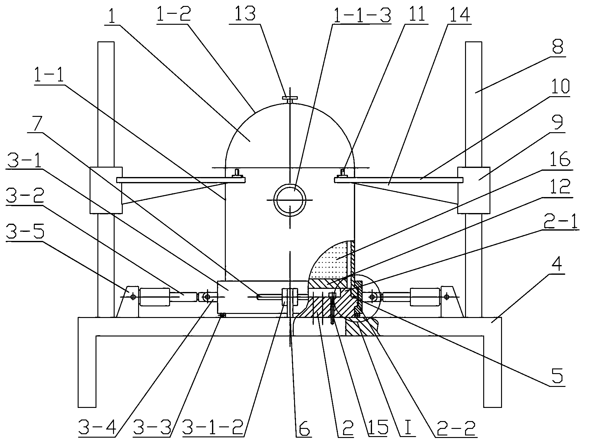
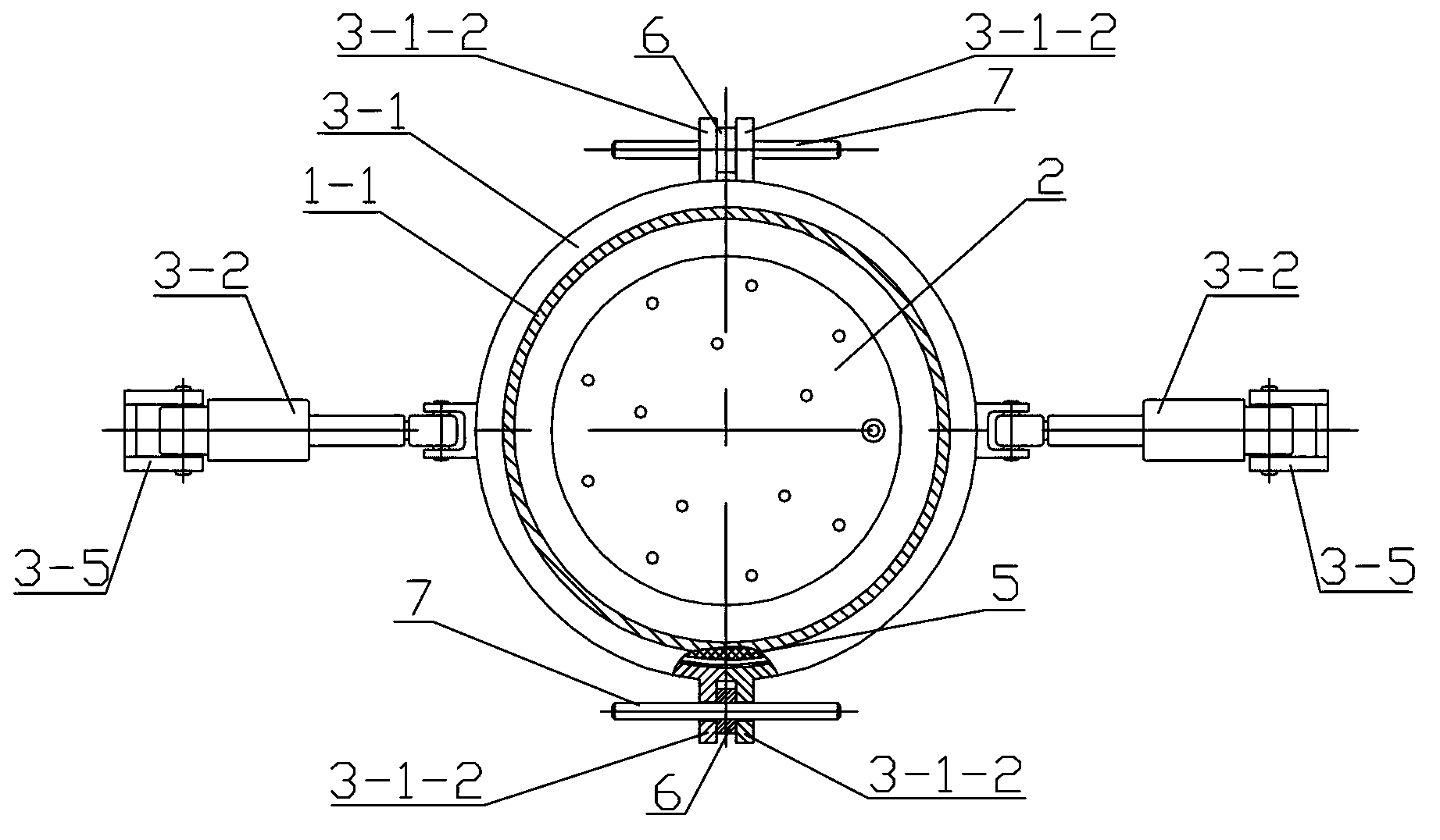
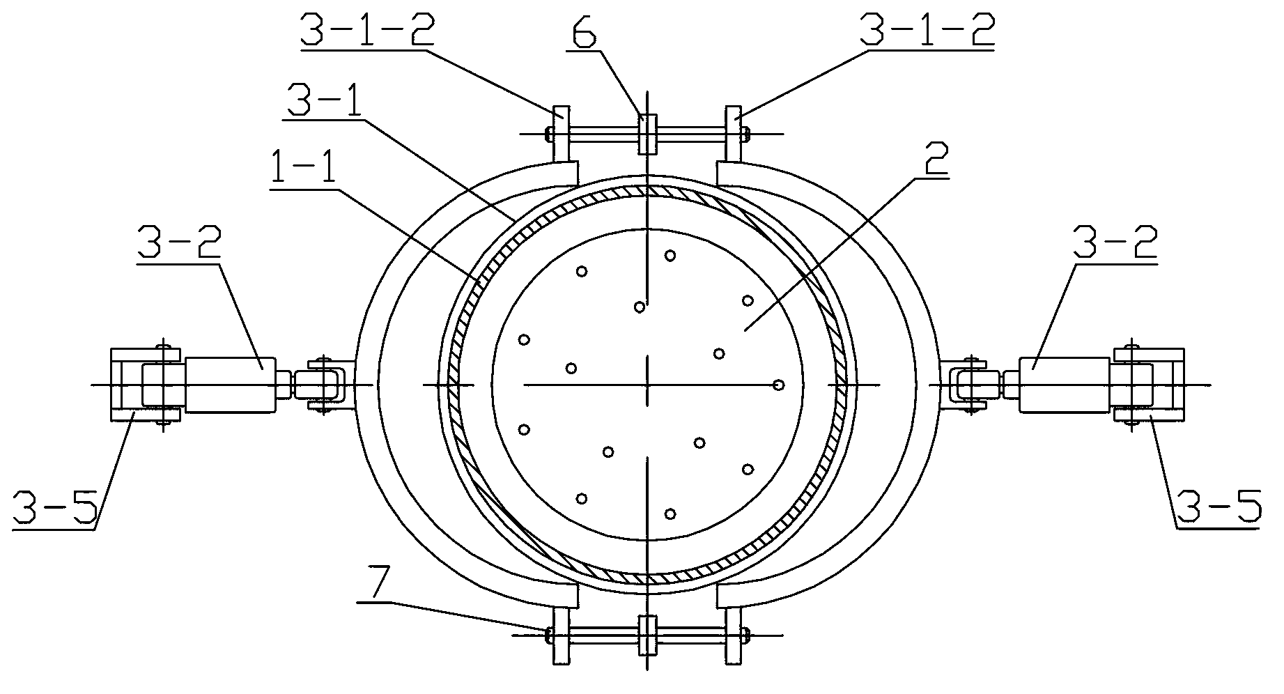
[0013] Specific implementation mode one: combine Figure 1 to Figure 5 Describe this embodiment, this embodiment includes a cabin body 1, a bilge 2, a platform support 4, an annular sealing ring 5, a welding platform 12, two clamp devices 3, two guide post supports 6, and two clamp guide posts 7. Two lifting guide rails 8, two lifting cylinders 9, two lifting frames 10, four lugs 11 and several tank penetration connectors 15, the upper end surface of the bilge 2 is provided with an annular boss along the edge 2-1, the outer surface of the annular boss 2-1 is provided with a guide slope 2-1-1 inclined from bottom to top and from outside to inside, and the guide slope 2-1-1 plays a role in guiding and positioning the cabin body 1 during its descent ; The outer wall of the bilge 2 is provided with a lower annular flange 2-2, and the lower end surface of the lower annular flange 2-2 is a lower slope 2-2-1 inclined from the outside to the inside and from the top to the bottom, and ...

specific Embodiment approach 2

[0014] Specific implementation mode two: combination figure 1 Describe this embodiment, the difference between this embodiment and specific embodiment 1 is that it also has two reinforcing ribs 14, the bottom of each lifting frame 10 is equipped with a reinforcing rib 14, and an end surface of the reinforcing rib 14 is connected with the lifting frame. The frame 10 is connected, and the other end face of the rib 14 is connected with the lifting cylinder 9. Other components and connections are the same as those in the first embodiment.

[0015] Working process of the present invention:

[0016](1), before using the present invention to carry out experimental welding: start two hoop opening and closing oil cylinders 3-2 and two lifting oil cylinders 9 at the same time, hoop opening and closing oil cylinder 3-2 drives the split hoop 3-1 to separate, The lifting cylinder 9 drives the lifting frame 10 to move upward, separating the cabin body 1 from the bilge 2; the experimental ...


PUM


Abstract

The invention disclose a welding experiment chamber for simulating a medium-pressure liquid or gas environment, and relates to an underwater welding experiment chamber. The welding experiment chamber aims to solve the problems that for the existing experimental equipment for simulating underwater welding, components in a chamber are not easy to replace, the applicability is poor, the simulated pressure for simulating a welding experiment is low, and only a single pressure medium is available. A chamber bottom is arranged on the upper end face of a platform support; a plurality of chamber penetrating connectors are uniformly arranged in the chamber bottom; a chamber body is arranged above the chamber bottom; two semicircular hoops are buckled to form a ring; two side walls of a trapezoidal groove are tightly matched with an upper inclined plane and a lower inclined plane; an oil cylinder support is fixedly connected with the upper end face of the platform support; two lifting guide rails are symmetrically arranged on the outer side of the oil cylinder support by adopting the vertical center line of the chamber body as a reference; each lifting guide rail is provided with a lifting oil cylinder; four lugs are uniformly distributed on the external wall at the upper end of a barrel; one end of each lifting support is connected with one of the lifting oil cylinders; the other end of each lifting support is connected with two of the four lugs; and a welding platform is arranged on an annular boss. The experiment chamber is used for simulating the underwater welding.

Description

technical field [0001] The invention relates to an underwater welding experiment cabin, in particular to a welding experiment cabin for simulating a medium-pressure liquid or gas environment. Background technique [0002] With the development of marine resources, a large number of steel structures are used in marine engineering, such as submarine oil pipelines, offshore drilling platforms, and sea-crossing bridges. Whether it is the construction of structures or the maintenance of facilities, underwater welding is required. Whether it is the construction of structures or the maintenance of facilities, underwater welding technology has irreplaceable advantages. Underwater wet welding can be applied to pressure environments where the water depth does not exceed 100 meters; when the water depth exceeds 100 meters, underwater high-pressure dry welding is generally used. Regardless of underwater wet welding or high-pressure dry welding, welding is performed in an environment hi...

Claims


Application Information

Patent Timeline
Patent Type & Authority Applications(China)
IPC IPC(8): B23K31/02
Inventor 李海超高洪明李凯巩杉陈弈
Owner HARBIN INST OF TECH
Why Eureka
Try Eureka