Real-time monitoring and safety warning device for temperature of furnace tube of tubular industrial furnace

A technology of real-time monitoring and safety warning, applied in the direction of furnaces, furnace components, lighting and heating equipment, etc., can solve problems such as difficulty in achieving the best effect of combustion control, failure to detect in time, hidden safety hazards, etc., and achieve the goal of eliminating the environment and emissivity impact, comprehensive and accurate recording and analysis, and accurate real-time monitoring of the effects

Active Publication Date: 2012-11-28
HEFEI RUISHI MEASUREMENT & CONTROL ENG TECH
View PDF3 Cites 24 Cited by
  • Summary
  • Abstract
  • Description
  • Claims
  • Application Information

AI Technical Summary

Problems solved by technology

[0005] At present, the temperature monitoring of the furnace tube of the heating furnace still relies on the staff to regularly measure the furnace tube with a temperature gun through the observation hole, so there are the following problems: (1) The number of measured points (areas) is limited, The actual distribution of the temperature of the furnace tube cannot be fully reflected, making it difficult to control the actual situation of the furnace tube in the entire furnace, and it is also dif

Method used


Image

  • Real-time monitoring and safety warning device for temperature of furnace tube of tubular industrial furnace
  • Real-time monitoring and safety warning device for temperature of furnace tube of tubular industrial furnace
  • Real-time monitoring and safety warning device for temperature of furnace tube of tubular industrial furnace

Examples


Embodiment Construction

[0025] The present invention will be further described below in conjunction with the embodiments and accompanying drawings.

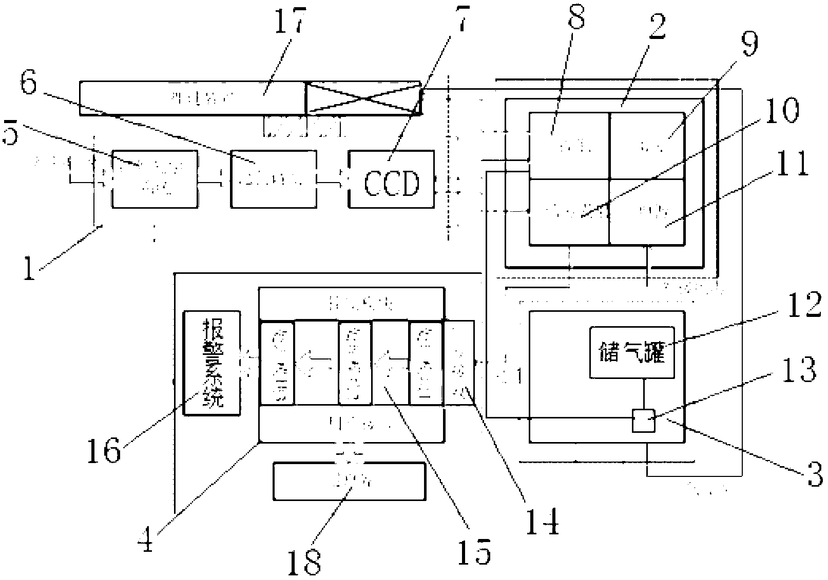
[0026] Such as figure 1 As shown, the tube-type industrial furnace tube temperature real-time monitoring and safety warning device mainly includes four parts: detection equipment 1, electrical control equipment 2, gas source control cabinet 3, and computer processing and control equipment 4. The detection equipment 1 includes High temperature monitoring probe, pneumatic propulsion device 17, high temperature monitoring probe includes infrared optical imaging system 5, colorimetric modulation 6, CCD imaging system 7, the outer side of high temperature monitoring probe is provided with cooling protection device and placed on the pneumatic propulsion device 17, high temperature The monitoring probe has a built-in temperature sensor. The electrical control equipment includes a digital controller 8, a status display module 9, a signal transmitter 10 and a po...


PUM


Abstract

The invention discloses a real-time monitoring and safety warning device for the temperature of a furnace tube of a tubular industrial furnace. The real-time monitoring and safety warning device comprises four parts, namely a detecting device, an electrical control device, an air source control cabinet and a computer process and control part. According to the characteristics of infrared radiation of the furnace tube, an infrared radiation image of the furnace tube is obtained by an optical imaging system suitable for colorimetric temperature measurement, the infrared radiation image is analyzed by adopting technologies of digital image processing, pattern recognition, computer vision measurement and the like, the distribution state of the temperature on the surface of the furnace tube is obtained in real time by virtue of the colorimetric temperature measurement technology so as to give an overtemperature alarm, and the change trend of the distribution of a temperature field of the furnace tube is obtained by utilizing a database to analyze history data in the whole operation cycle of the furnace tube so as to provide intuitive and effective basis for the evaluation of the efficiency of a heating furnace and the residual service life of the furnace tube. The real-time monitoring and safety warning device provides key parameters for the optimization of burning of the industrial furnace, and has great significance on ensuring safety production and improving productive efficiency.

Description

technical field [0001] The invention relates to the field of tubular industrial furnaces in the petrochemical industry, in particular to a real-time monitoring and safety warning device for the furnace tube temperature of the tubular industrial furnace. Background technique [0002] Tube industrial furnace is one of the main equipments in petrochemical production and is widely used in petroleum refining and petrochemical production. However, because the materials handled are flammable and explosive, coupled with the open flame operation, the danger is very high, and it has always been the key part of fire prevention and explosion protection in the production process of petrochemical enterprises. The heating furnace often adopts a tubular heating furnace. The low-temperature material passes through the convection chamber furnace tube and the radiation chamber furnace tube, absorbs heat in the furnace, and reaches the required process requirements when it exits the heating fur...

Claims


Application Information

Patent Timeline
IPC IPC(8): F27D21/00F27D21/04
Inventor 仓亚军唐磊刘纯红钟核俊王鹏陈明武
Owner HEFEI RUISHI MEASUREMENT & CONTROL ENG TECH
Why Eureka
Try Eureka