
High-speed photon correlator with large dynamic range

A photon correlator, a technology with a large dynamic range, which is used in instruments, scientific instruments, measuring devices, etc., can solve the problems of high cost of correlators and unstable baselines of correlation functions, so as to improve the dynamic range, speed and stability. Effect

Inactive Publication Date: 2014-06-11
SHANDONG UNIV OF TECH
View PDF5 Cites 0 Cited by
  • Summary
  • Abstract
  • Description
  • Claims
  • Application Information

AI Technical Summary

Problems solved by technology

The correlator based on FPGA can not only increase the speed of the correlation operation, but also expand the dynamic range, but with the increase of the number of channels, the cost of the correlator will become very expensive, and there is also the problem of unstable baseline of the correlation function

Method used


Image

  • High-speed photon correlator with large dynamic range
  • High-speed photon correlator with large dynamic range
  • High-speed photon correlator with large dynamic range

Examples


Embodiment approach 1

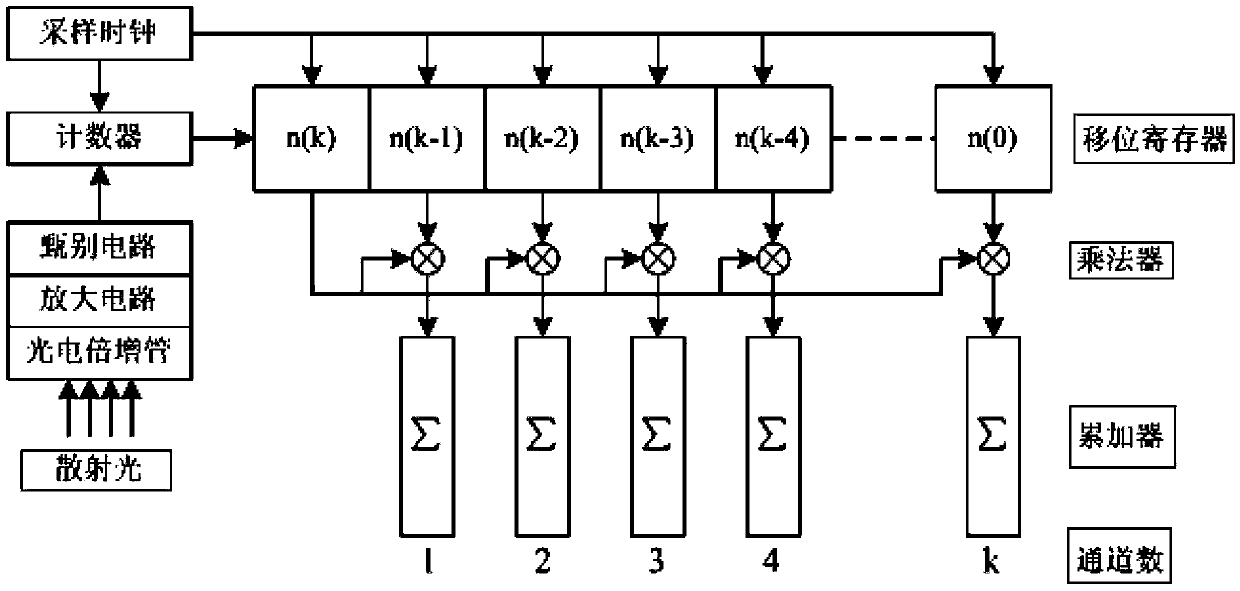
[0078] refer to Figure 8 , the channel structure of the first group of correlation operation is composed of 16 correlation channels. The photon pulse signal is input through the input terminal CIN of the photon counting module Counter, and is counted under the driving of the rising edge of the sampling clock CLK, and the obtained count value is output by the output terminal Q[15:0] of the photon counting module Counter, and then sent to Input B[15:0] of the 16 associated channels and input A[15:0] of the first associated channel. After the photon count value forms a delay of one sampling clock cycle in the relevant channel, it is output from the output terminal AO[15:0] of the previous relevant channel to the input terminal A[15:0] of the next relevant channel. Each relevant channel performs multiplication and accumulation operation on the photon count value input from the input terminal A[15:0] and B[15:0], and the obtained correlation function value is sent to the multi-ch...

Embodiment approach 2

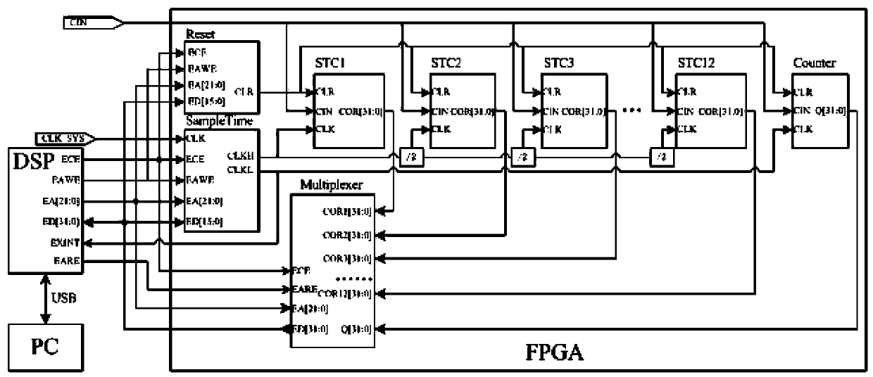
[0080] refer to Figure 9, the structure of the second group of correlation operation channels is similar to that of the first group of correlation operation channels, except that a delay unit Delay8 is added to the second group of correlation operation channels, and after the count value of the photon counting module Counter is delayed by 8 sampling clock cycles, Then carry out the correlation calculation, the obtained correlation function value, and the total sampling times and total photon count value output by the monitoring channel Monitor are sent to the multiplexer Multiplexer, and output to the DSP chip circuit from the port COR[31:0] in turn . From the second group, the structure of each channel group is exactly the same.

[0081] The present invention is based on a photon correlator combining a high-speed channel and a low-speed channel. The calculation method of its dynamic range is as follows: the FPGA chip circuit contains 12 groups of correlation channels, the f...


PUM


Abstract

The invention relates to the technical field of granularity measurement of a photon correlation spectroscopy and particularly relates to a photon correlator. The high-speed photon correlator with a large dynamic range comprises a photon correlator; the photon correlator comprises channels and the channels comprise a high-speed channel and a low-speed channel; the high-speed photon correlator further comprises an FPGA (Field Programmable Gate Array) chip circuit, a DSP (Digital Signal Processor) chip circuit and a computer; and the DSP chip circuit is respectively connected with the FPGA chip circuit and the computer. The FPGA chip circuit is used for computing the high-speed channel and the DSP chip circuit is used for computing the low-speed channel. According to the high-speed photon correlator with the large dynamic range disclosed by the invention, based on the structure combining the high-speed channel and the low-speed channel, fewer hardware resources are utilized, so that a dynamic range of the correlator is improved and the high-speed correlation computation is realized; and meanwhile, the cost of the correlator is reduced.

Description

technical field [0001] The invention relates to the technical field of photon correlation spectroscopy particle size measurement, in particular to a photon correlator. Background technique [0002] Photon correlation spectroscopy is an effective method to study the dynamic characteristics of the sample. The sample particles cause fluctuations in the intensity and frequency of the scattered light due to Brownian motion. By measuring the autocorrelation function of the light intensity of the scattered light, the dynamic information of the particle system can be obtained. The photon correlator is the core device of the photon correlation spectroscopy nanoparticle particle size measurement system. The device is used to count the photon pulses of scattered light, and perform real-time autocorrelation calculations to obtain autocorrelation functions to obtain the time correlation of scattered light. information. Photon correlation calculations can be realized by software or hardw...

Claims


Application Information

Patent Timeline
Patent Type & Authority Patents(China)
IPC IPC(8): G01N15/14G01N15/02G01J11/00
Inventor 刘伟陆文玲申晋魏佩瑜马立修李震梅
Owner SHANDONG UNIV OF TECH
Learn More