Sectional type groove type solar energy condenser

A trough solar and concentrator technology, applied in the field of solar concentrators, can solve the problems of high technological requirements and high cost of parabolic supports

Inactive Publication Date: 2012-11-28
UNIV OF SCI & TECH OF CHINA
View PDF7 Cites 20 Cited by
  • Summary
  • Abstract
  • Description
  • Claims
  • Application Information

AI Technical Summary

Problems solved by technology

Xu Yongbang and others proposed a new trough-type parabolic solar concentrator (Xu Yongbang, Wang Fang, Deng Xia. A trough-type parabolic solar concentrator 201020563001.4), and a plane reflector is installed on the parabolic support to avoid Using a high-cost integral curved mirror reduces the cost, but the process requirements for the parabolic support are also very high

Method used


Image

  • Sectional type groove type solar energy condenser
  • Sectional type groove type solar energy condenser
  • Sectional type groove type solar energy condenser

Examples


Embodiment 1

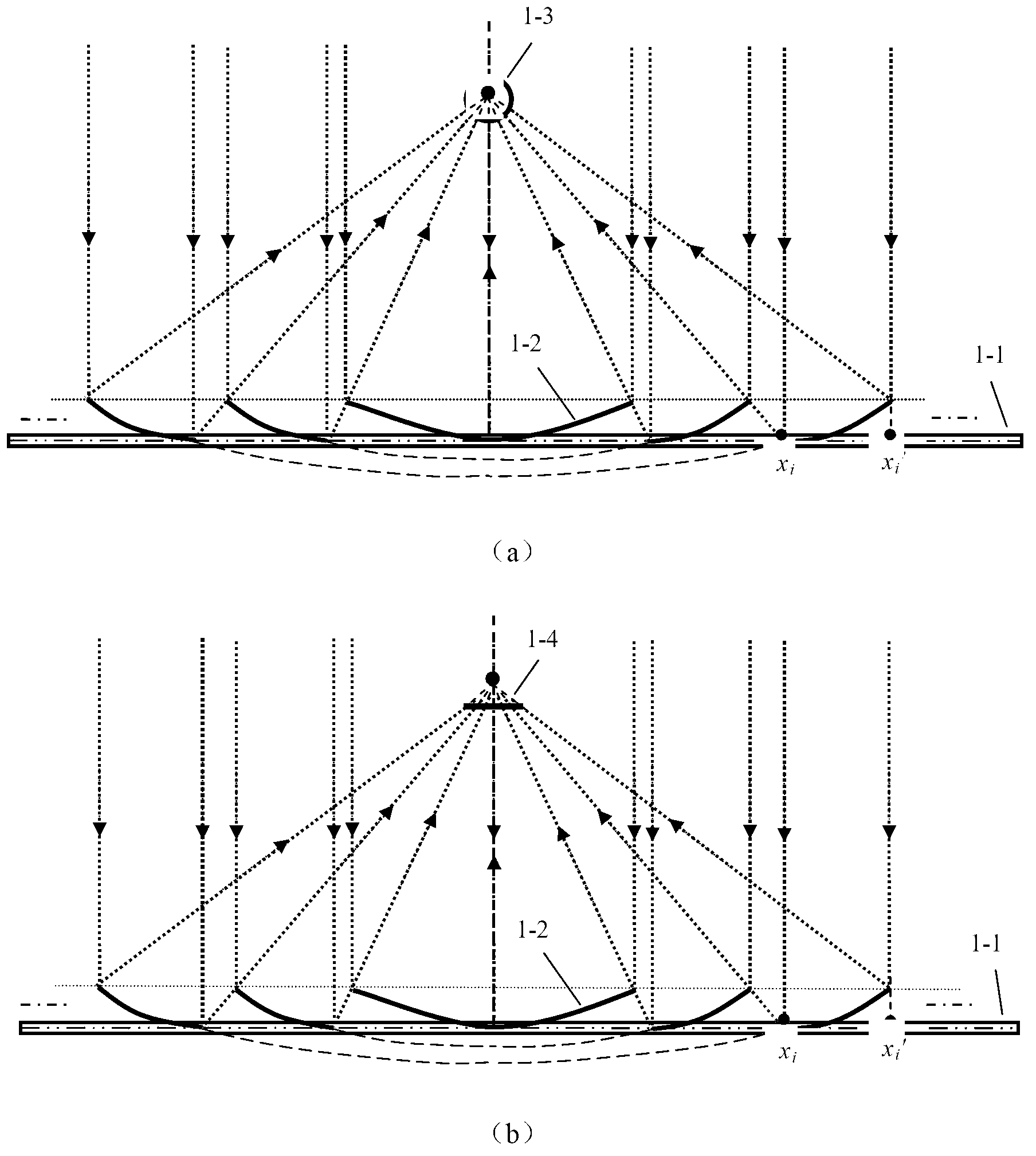
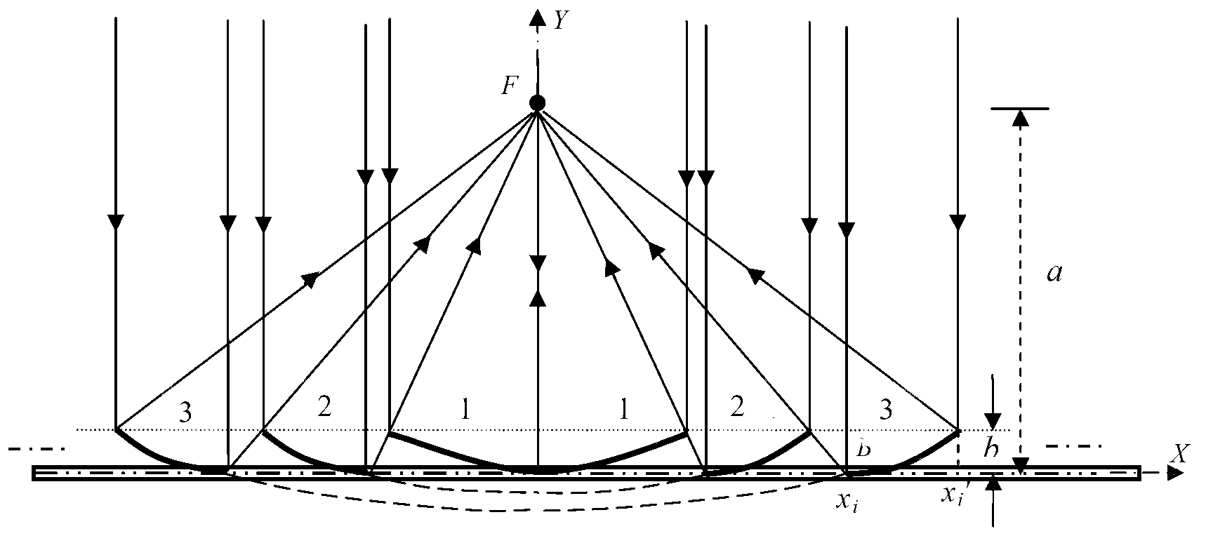
[0038] Embodiment 1, for the schematic structure of the segmented trough solar concentrator used for the heat utilization of the receiver as a cylinder, see figure 1 (a), the cylindrical light concentrating receiver 1-3 is a cylindrical vacuum tube heat collector, its radius is R, the vertical height between its center line and the flat frame 1-1 is a, and one of all parabolic reflectors 1-2 One side is fixed on the flat frame 1-1, and the displacement of the other side away from the flat frame 1-1 is b. like figure 1 As shown in (a), all the light rays reflected by the parabolic reflector 1-2 fall on the surface of the cylindrical light-condensing receiver 1-3, and the focal line of each parabolic reflector 1-2 is at the center of the cylindrical receiver 1-3 line position. The parabolic reflectors 1-2 are sequentially arranged on the plane frame 1-1, and the light reflected by the latter parabolic reflector 1-2 just passes through the edge of the previous parabolic refle...

Embodiment 2

[0049] Example 2, the structure of segmented trough solar concentrators for planar concentrating light and heat utilization can be found in figure 1 (b), the plate-shaped concentrating receiver 1-4 is a plate-shaped heat collector with a width of L, placed parallel to the plate frame 1-1, and the vertical height from the plate frame 1-1 is a, and all parabolic reflectors 1 One side of -2 is fixed on the flat frame 1-1, and the displacement of the other side away from the flat frame 1-1 is b. The light reflected by the parabolic reflector 1-2 all falls on the flat heat collector, and the focal lines of all the parabolic reflectors are at the same place above the flat heat collector. Because the sun's rays have a cone angle, the reflected light of the outermost parabolic reflector in the application falls as far as possible in the middle of the flat plate collector, so that as much light as possible can be irradiated on the surface of the flat plate collector. The parabolic re...

Embodiment 3

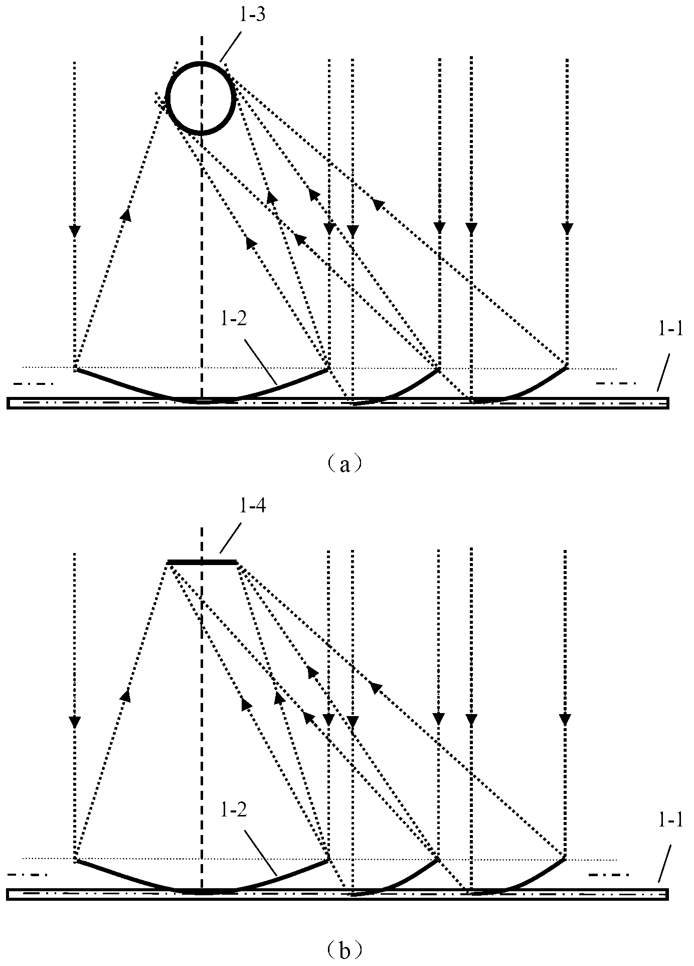
[0056] Embodiment 3, the structure of the segmented trough solar concentrator used for the heat utilization of the receiver as a cylinder is shown in image 3 (a), the radius of the cylindrical light concentrating receiver 1-3 is R, the vertical height between its center line and the flat frame 1-1 is a, and one side of all parabolic reflectors 1-2 is fixed on the flat frame 1-1 , the displacement of the other side away from the plate frame 1-1 is b. The edge of the light reflected by the parabolic reflector 1-2 falls on or within the boundary of the cylindrical light-concentrating receiver 1-3, and the parabolic reflector 1-2 is sequentially arranged on the plane frame 1-1, and the latter parabolic reflector 1-2 The reflected light just passes the edge of the previous parabolic reflector 1-2. The flat frame 1-1 is fixed on the sun tracking frame. The angle between the normal line of the plane frame of the single-axis solar tracker and the horizontal plane tracks the sun’s al...


PUM


Abstract

The invention discloses a sectional type groove type solar energy condenser which comprises a flat frame (1-1), parabolic reflectors (1-2), a cylindrical condensation receiver (1-3) or flat condensation receiver (1-4), wherein a plurality of parabolic reflectors (1-2) are sequentially arranged on the flat frame (1-1). The position, curvatures and opening widths of the parabolic reflectors (1-2) change with a focal line; in order to achieve the optical condensation effect, effective light rays reflected by the parabolic reflectors (1-2) all fall in an effective area of the cylindrical condensation receiver (1-3) or flat condensation receiver (1-4), light rays reflected by one reflection mirror surface behind exactly pass through the edge of the previous reflection mirror surface, the space of the flat frame (1-1) is maximally utilized and the light rays can not be shielded; and the flat frame (1-1) is fixed on a solar tracking frame. According to the sectional type groove type solar energy condenser, the pressure resistance against the wind is increased, the condensation ratio is increased within a limited area range, higher heat collection temperature is obtained and the industrial application is facilitated.

Description

technical field [0001] The invention relates to a novel solar concentrator, in particular to a segmented trough solar concentrator. Background technique [0002] The development and utilization of solar energy has become one of the main strategic decisions for the sustainable development of countries all over the world. However, the energy flux density of solar energy is low (about 1kW / m 2 ) has become one of the main obstacles to utilizing solar energy. In order to increase the radiant energy flow density of solar energy, the method of concentrating sunlight can be used to concentrate sunlight on the receiver, which can increase the temperature of heat collection when performing photothermal utilization, and reduce the consumption of expensive photovoltaic cells when performing photovoltaic power generation. Therefore, the development of low-cost, high-efficiency, and high-stability solar concentrators with practical value can further promote the widespread application of...

Claims


Application Information

Patent Timeline
Patent Type & Authority Applications(China)
IPC IPC(8): G02B19/00G02B7/182F24J2/12F24S23/71
CPCY02E10/42F24S23/74F24S2023/872Y02E10/40Y02P80/20
Inventor 胡芃张谦
Owner UNIV OF SCI & TECH OF CHINA
Why Eureka
Try Eureka