P-waveband high-power broadband element antenna

A vibrator antenna, high-power technology, applied in antennas, antenna parts, antenna supports/installation devices, etc., can solve the problems of small power capacity and narrow bandwidth of vibrator antennas, reduce weight, improve work efficiency and power, The effect of reducing reflection loss

Active Publication Date: 2012-11-28
SHANGHAI SPACEFLIGHT INST OF TT&C & TELECOMM
View PDF3 Cites 3 Cited by
  • Summary
  • Abstract
  • Description
  • Claims
  • Application Information

AI Technical Summary

Problems solved by technology

[0006] In order to solve the problems of narrow bandwidth and small power capacity of existing dipole antennas, the purpose of the present invention is to provide a high-power broadband dipole antenna

Method used


Image

  • P-waveband high-power broadband element antenna
  • P-waveband high-power broadband element antenna
  • P-waveband high-power broadband element antenna

Examples


Embodiment

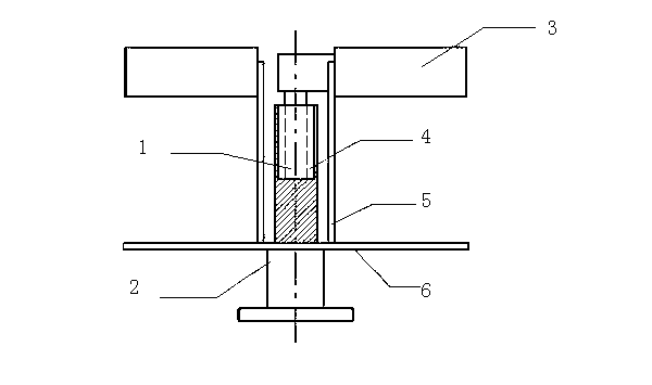
[0020] figure 1 It is a structural diagram of the P-band high-power broadband dipole antenna of the present invention. Such as figure 1 As shown, the device includes: a vibrator 3, a tuning rod 1, a tuning cavity 4, a vertical plate 5, a power feed seat 2 and a base 6, the power feed base 2 is vertically arranged on the lower side of the base 6, and the sleeve formed by the vertical plate 5 The cylinder is vertically arranged on the upper side of the base 6, and a tuning cavity 4 is provided in the sleeve, and a tuning rod 1 is provided in the tuning cavity 4, and two vibrators 3 are symmetrically installed on both sides of the upper end of the sleeve formed by two vertical plates 5 .

[0021] A coaxial feed interface is installed on the antenna base 6 and is connected to the signal transmission source; a balanced feed structure in the form of a grid is between the coaxial feed interface and the vibrator arm. Using the series compensation technology, the design of the conve...


PUM

PropertyMeasurementUnit
Widthaaaaaaaaaa

Abstract

The invention relates to radio communication equipment and discloses a P-waveband high-power broadband element antenna which comprises an antenna element, a tuning post, a tuning cavity, a vertical post, a feed seat and a base seat, wherein a coaxial feed connector is installed on the antenna base seat and is connected with a signal transmitting source, and a balance feed structure in the form of a grid plate is arranged between the coaxial feed connector and the element. The power capacity is 3 times of that of the conventional coaxial wire balance feed, the standing wave bandwidth of the element antenna is broadened, and the bandwidth on a carrier with the standing-wave ratio smaller than 1.3 can reach 20% which is 2 times of the bandwidth of the conventional element antenna structure. The invention solves the problems of narrow bandwidth, small power capacity and the like of the traditional element antenna and has the advantages of broad band, compact structure, high power resistance and the like.

Description

technical field [0001] The invention relates to radio communication equipment, in particular to a P-band high-power broadband dipole antenna. Background technique [0002] The antenna vibrator is a component on the antenna, which has the function of guiding and amplifying electromagnetic waves, so that the electromagnetic signal received by the antenna is stronger. The antenna vibrator is made of metal with good conductivity. Some vibrators are rod-shaped, and some have more complex structures. Generally, many vibrators are arranged in parallel on the antenna. [0003] At present, known dipole antennas have disadvantages such as narrow bandwidth and small power capacity. [0004] At present, there are methods to widen the bandwidth such as parallel resonant circuit loading in China, but the structure is relatively complicated and the power capacity is limited. [0005] Contents of the invention [0006] In order to solve the problems of narrow bandwidth and small power...

Claims


Application Information

Patent Timeline
IPC IPC(8): H01Q1/00H01Q1/12H01Q1/36
Inventor 金伟清章泉源
Owner SHANGHAI SPACEFLIGHT INST OF TT&C & TELECOMM
Why Eureka
Try Eureka