High-speed motor with solid rotor

A high-speed motor, solid rotor technology, applied in asynchronous induction motors, electric components, electrical components, etc., can solve the problem of difficulty in manufacturing high-speed motors, and achieve the effect of increasing the critical speed, expanding the manufacturing range, and improving the critical speed and deflection.

Inactive Publication Date: 2012-11-28
SHANGHAI PINXING EXPLOSION PROOF MOTOR
View PDF6 Cites 6 Cited by
  • Summary
  • Abstract
  • Description
  • Claims
  • Application Information

AI Technical Summary

Problems solved by technology

However, in the manufacture of large-capacity and high-speed motors, the traditional structure of stacked rotor punches can no longer meet the structural requirements of centrifugal force. Due to the limitations of critical speed and deflection, it is difficult to manufacture high-power, high-speed motors with stacked rotor punches.

Method used


Image

  • High-speed motor with solid rotor
  • High-speed motor with solid rotor
  • High-speed motor with solid rotor

Examples


Embodiment Construction

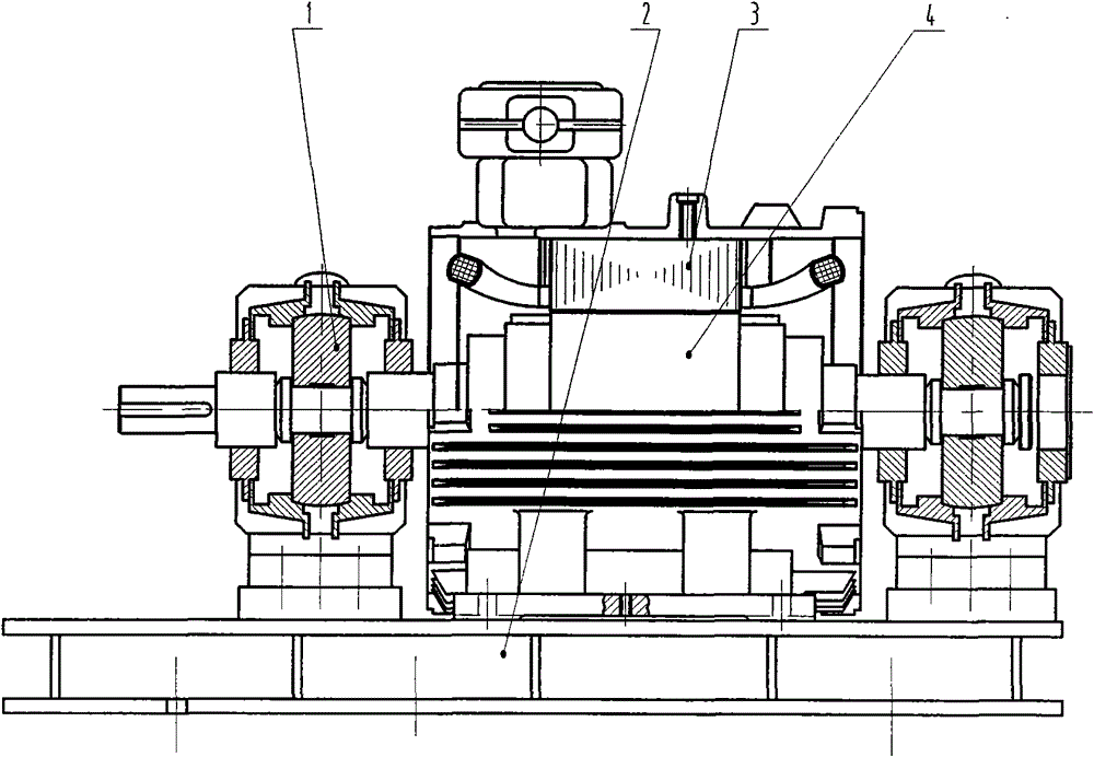
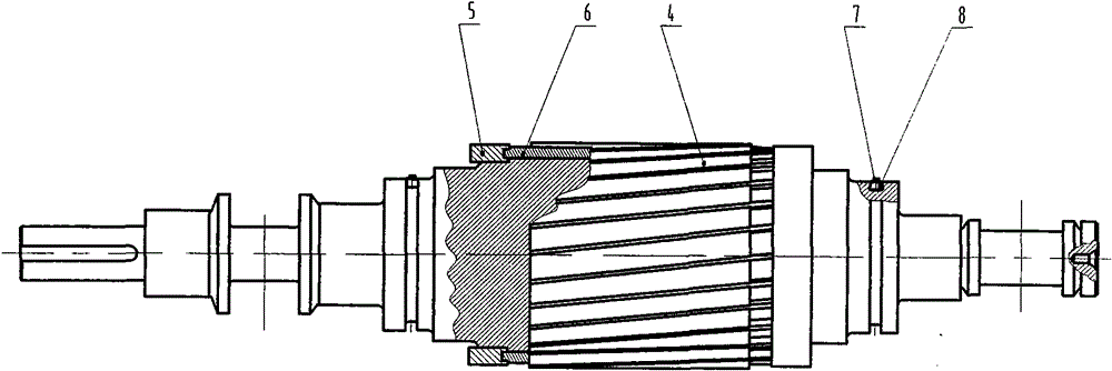
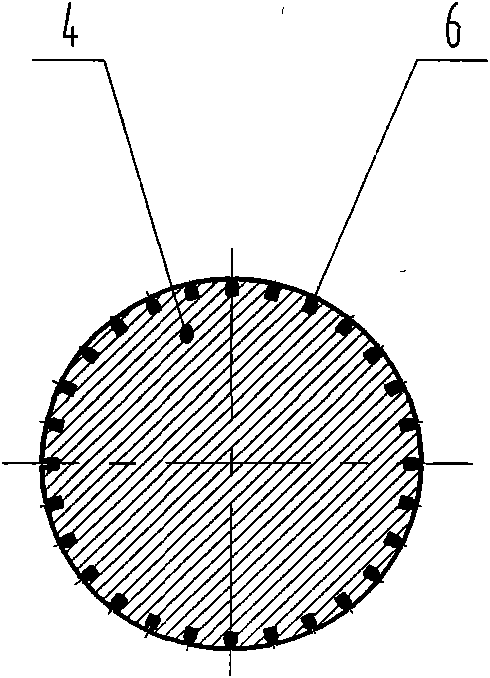
[0010] exist figure 1 Among them, the tilting pad high-speed sliding bearing (1) and the motor stator (3) are installed on the chassis (2), and the rotor core (4) is supported by the tilting pad high-speed sliding bearing (1) to maintain contact with the motor stator (3). Concentricity. In order to improve the torque of the motor, slots are made on the surface of the rotor iron core (4), and the rotor guide bar (6) is inlaid, and the two ends of the rotor guide bar (6) are welded together with the rotor end ring (5). Form a mouse cage. Slots are installed at both ends of the rotor iron core (4) to install balance weights (8) and balance screws (7). Improve the accuracy of dynamic balance.


PUM


Abstract

The invention discloses a high-speed motor with a solid rotor. A laminated structure for punching of the iron core of the conventional motor rotor is changed; the iron core of the rotor is manufactured through a solid rotating shaft; the diameter of the rotating shaft is increased to an extreme size, so that the extreme rotating speed of the motor is increased; and a slot is formed in the surface of the rotating shaft, and a copper conductive strip is embedded into the slot and welded with copper end rings at two ends, so that the high-speed motor which has the power of below 400 KW and is used for starting and running a mouse cage is formed. By the structure, the high-speed motor can run in a speed range of 0 to 20,000 r/min.

Description

Technical field [0001] The invention relates to a high-speed motor with a power greater than 50KW and a rotational speed higher than 10000r / min. In the equipment that requires high speed, the use of high-speed motors can cancel the speed-increasing device and directly drive high-speed fans and water pumps. Background technique [0002] As we all know: high-speed fans, water pumps and other machinery industries. A high-speed prime mover is often required to drag the host. In the past, OEMs mostly used speed-increasing gearboxes or multi-stage blades to solve the problem. Increased the complexity of the weight, volume and processing of the equipment. The speed of the motor can be increased by using a variable frequency power supply. However, in the manufacture of large-capacity and high-speed motors, the traditional structure of stacked rotor punches can no longer meet the structural requirements of centrifugal force. Due to the limitations of critical speed and deflection...

Claims


Application Information

Patent Timeline
Patent Type & Authority Applications(China)
IPC IPC(8): H02K17/16H02K7/04
Inventor 李凯
Owner SHANGHAI PINXING EXPLOSION PROOF MOTOR
Why Eureka
Try Eureka