Integrated pump and injector for exhaust after treatment

A technology of injector and integrated pump, which is applied in the direction of exhaust treatment, exhaust device, machine/engine, etc., can solve the problems of high cost, complexity, and additional, and achieve the effect of reduced power consumption and low pressurized volume

Inactive Publication Date: 2012-11-28
斯塔纳迪恩公司
View PDF5 Cites 36 Cited by
  • Summary
  • Abstract
  • Description
  • Claims
  • Application Information

AI Technical Summary

Problems solved by technology

[0007] It is well known in the industry that all SCR urea syst

Method used


Image

  • Integrated pump and injector for exhaust after treatment
  • Integrated pump and injector for exhaust after treatment
  • Integrated pump and injector for exhaust after treatment

Examples


Embodiment Construction

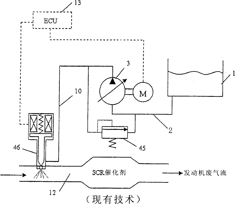
[0034] figure 1 is a schematic representation of a prior art airless system outlined in the Background section.

[0035] Urea solution is stored in storage tank 1 and passes through line 2 from where it enters pump 3 . The pump 3 is driven by an electric motor. The motor is driven and controlled by an electronic control unit (ECU) 13 to deliver sufficient volume through line 10 and into injector 46 . A substantially constant pressure is maintained in the line 10 and in the injector 46 by means of a regulator 45 which is either a separate component or integrated in the pump 3 . Injector 46 is electromagnetically operated and is controlled and powered by ECU 13 . The injector delivers an atomized urea solution into the engine exhaust 12 where the atomized urea solution can react with the SCR catalyst. The control of the injection quantity is determined by the operating frequency and duration of the injector opening. Storage tank 1 and lines 2 and 10 are heated to avoid free...


PUM


Abstract

A urea solution injection system and an injector with which urea solution or other exhaust treatment liquid from a source tank can be injected as an atomized spray into an exhaust pipe. A metering pump with integrated injection nozzle are contained in a common housing mounted directly to the exhaust pipe, thereby eliminating the separate electric motor driven pump, line between pump, and injector in conventional systems.

Description

Background technique [0001] Emission standards for vehicles with internal combustion engines continue to become more stringent. For on-highway or off-highway vehicles with diesel engines, a common exhaust aftertreatment to reduce NOx emissions is to use a Selective Catalytic Converter (SCR) in the tailpipe. The desired chemical reaction in the SCR can be promoted by injecting a urea solution into the exhaust pipe upstream of the SCR device. [0002] Usually, special filter traps or similar filter devices are also located in the exhaust pipe. Such devices must be periodically regenerated, commonly by injecting a hydrocarbon liquid into the exhaust gas stream, the combustion of which generates sufficient heat to regenerate the device. [0003] It would be desirable to provide similar injectors for use with SCR devices and filter devices. [0004] There are currently two known types of SCR urea systems in use. [0005] One system includes an air pump, a urea solution storage ...

Claims


Application Information

Patent Timeline
IPC IPC(8): F01N3/20
CPCF01N2610/1433F01N3/2066Y02T10/24F01N2610/02F01N2610/14F01N2610/144Y02T10/12
Inventor 马克·S·卡瓦纳罗伯特·G·卢卡斯叶夫根尼·诺尔金
Owner 斯塔纳迪恩公司
Why Eureka
Try Eureka