Oil cooling system for double-chamber vacuum oil quenching furnace

An oil cooling system and cooling system technology, applied in quenching devices, heat treatment equipment, manufacturing tools, etc., can solve the problems of inability to adjust the speed of quenching oil cooling, inconvenient maintenance, and lack of direction in the flow of quenching oil, so as to ensure uniform cooling performance, easy maintenance and installation

Inactive Publication Date: 2012-12-05
SUZHOU INDAL PARK JIESHITONG VACUUM TECH
View PDF10 Cites 4 Cited by
  • Summary
  • Abstract
  • Description
  • Claims
  • Application Information

AI Technical Summary

Problems solved by technology

[0003] 1. The cooling speed of the quenching oil cannot be adjusted, so it cannot be adjusted in real time according to the cooling process of the workpiece;
[0004] 2. Since the stirring motor is set at the lower part of the fuel tank, and the rotating shaft of the stirring motor is set on the side of the fuel tank, on

Method used


Image

  • Oil cooling system for double-chamber vacuum oil quenching furnace

Examples


Embodiment Construction

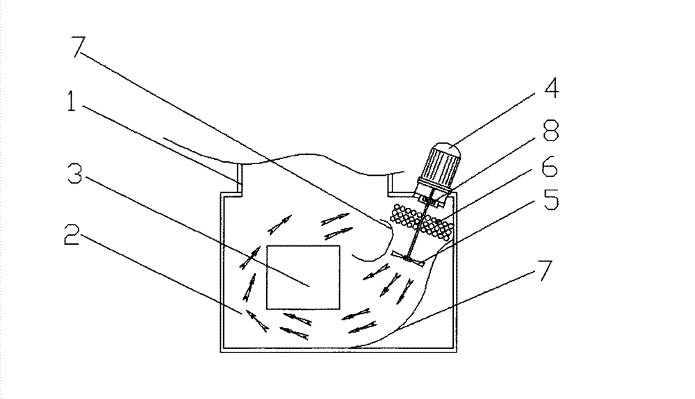
[0014] figure 1 The oil cooling system of a double-chamber vacuum oil quenching furnace shown includes a furnace body 1 and an oil tank 2. The oil tank 2 is arranged under the furnace body 1, and quenching oil is stored therein. The workpiece 3 to be quenched is placed in the oil tank 2. The oil tank 2 is provided with a quenching oil cooling device, including a stirring motor 4, an impeller 5 and a heat exchanger 6. The heat exchanger 6 is arranged on the transmission shaft of the stirring motor, and the impeller 5 is arranged at the end of the transmission shaft of the agitator motor. In order to improve the cooling effect of the workpiece, the convenience of use and maintenance, and the diversion of the quenching oil, the stirring motor is installed obliquely above the oil tank; both sides of the impeller in the oil tank 2 are provided with annular deflectors 7, and the two sides of the annular deflectors 7 are respectively connected to the The two sides of the oil tank 2 a...


PUM


Abstract

The invention discloses an oil cooling system for a double-chamber vacuum oil quenching furnace. The oil cooling system comprises a furnace body and an oil tank, wherein a quenching oil cooling device is arranged on the oil tank; the quenching oil cooling device comprises a stirring motor, an impeller and a heat exchanger, wherein the heat exchanger is arranged on the transmission shaft of the stirring motor; and the impeller is arranged at the tail end of the transmission shaft of the stirring motor. The oil cooling system is characterized in that the stirring motor is arranged above the oil tank in an inclined way; annular flow guide plates are arranged on both two sides of the impeller in the oil tank; the two side surfaces of each annular flow guide plate are respectively welded with the two side surfaces of the oil tank; a thermocouple oil temperature detection device is arranged on the heat exchanger; and the signal feedback end of the thermocouple oil temperature detection device is connected with a water supply system of the heat exchanger and automatically controls the water supply system of the heat exchanger. The stirring motor is arranged above the oil tank in an inclined way, so that the problem of inconvenience in maintenance after the oil tank leaks is solved; and the control over the oil temperature is realized by controlling the flow rate of water supply by sending the feedback information to an automatic control valve in the water supply system of the heat exchanger by the thermocouple oil temperature detection device.

Description

technical field [0001] The invention relates to an oil cooling system for a double-chamber vacuum oil quenching furnace, in particular to an oil cooling system for a double-chamber vacuum oil quenching furnace with adjustable oil cooling speed and convenient maintenance. Background technique [0002] The thermal stirring system of the current vacuum oil quenching furnace is often designed in the lower part of the oil tank, specifically: a horizontal shaft is set at the bottom of the oil tank, one end of the horizontal shaft is placed in the oil tank, an impeller is installed on the horizontal shaft in the oil tank, and the horizontal shaft The other end of the tank exceeds the side of the oil tank, and is sealed with the side of the oil tank through a seal, and a stirring motor that drives the horizontal axis to rotate is installed at its end. But there are following problems in this way: [0003] 1. It is impossible to adjust the cooling speed of the quenching oil, so that...

Claims


Application Information

Patent Timeline
IPC IPC(8): C21D1/63C21D1/773
Inventor 李荣华
Owner SUZHOU INDAL PARK JIESHITONG VACUUM TECH
Why Eureka
Try Eureka