Air preheater and application thereof

An air preheater and cold air technology, which is applied in the field of flue gas waste heat recovery, can solve the problem of not solving the problem of unsolved flue gas condensation and releasing latent heat to preheat air, etc.

Inactive Publication Date: 2012-12-05
CHINA PETROLEUM & CHEM CORP +1
View PDF8 Cites 10 Cited by
  • Summary
  • Abstract
  • Description
  • Claims
  • Application Information

AI Technical Summary

Problems solved by technology

[0009] The air preheater in the prior art only solves the heat storage problem of reducing the temperature of the hot gas, but does not solve the problem of flue gas condensing in the heat storage chamber to release latent heat to preheat the air, and the hot air is used for combustion in the heating furnace

Method used


Image

  • Air preheater and application thereof
  • Air preheater and application thereof
  • Air preheater and application thereof

Examples


Embodiment Construction

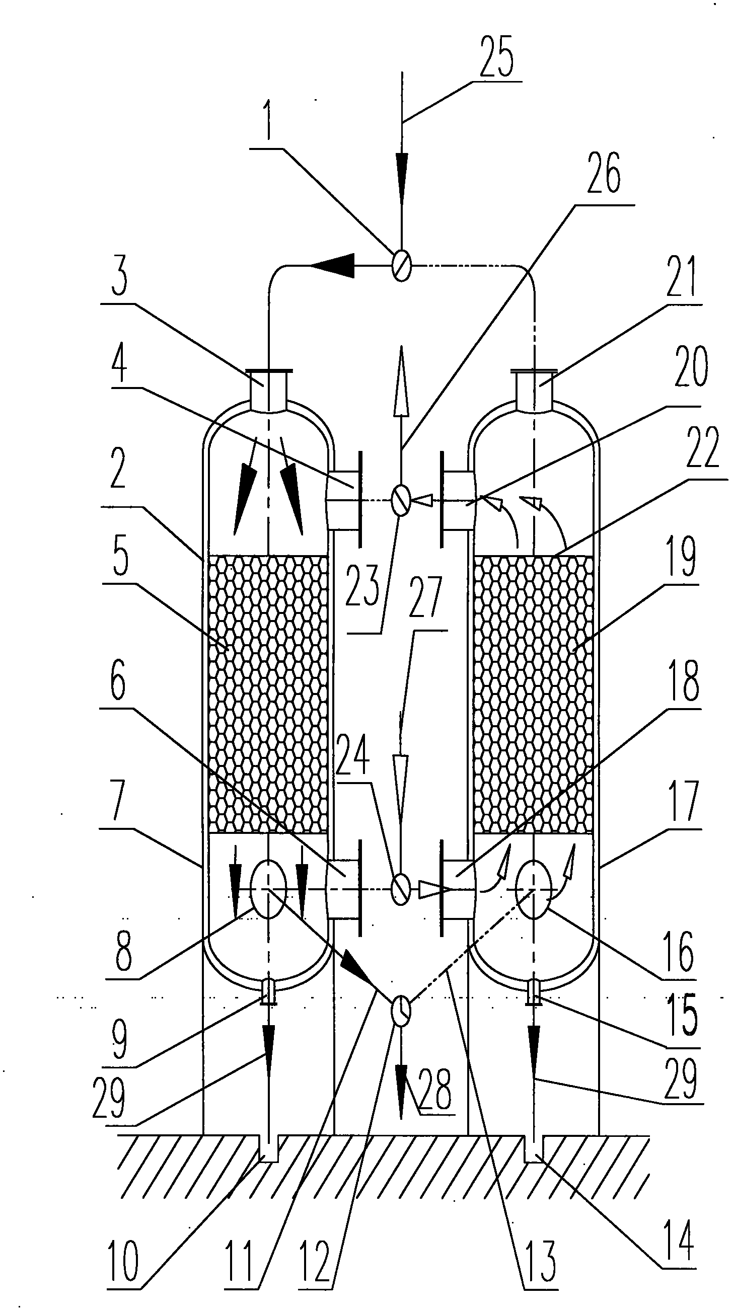
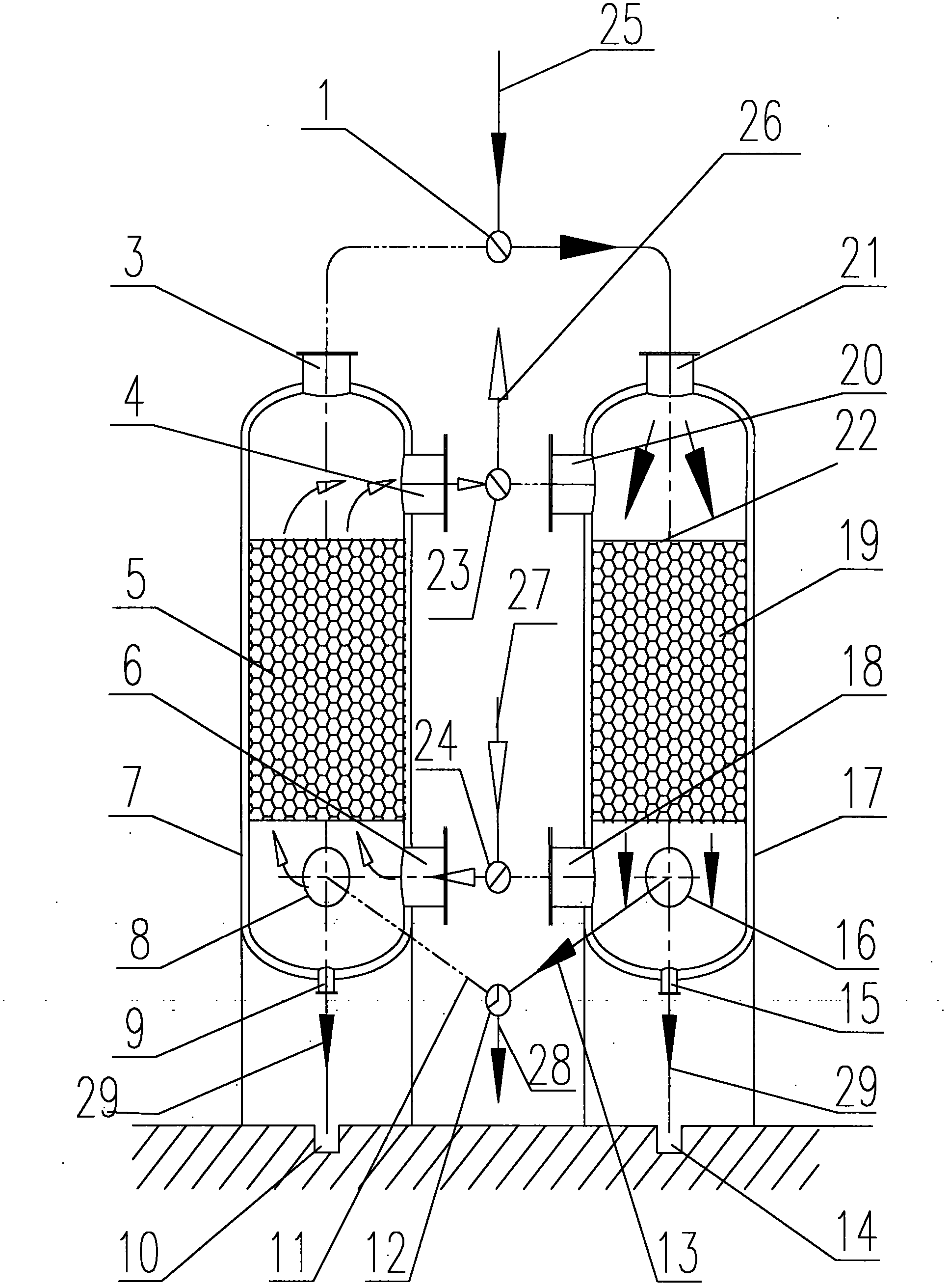
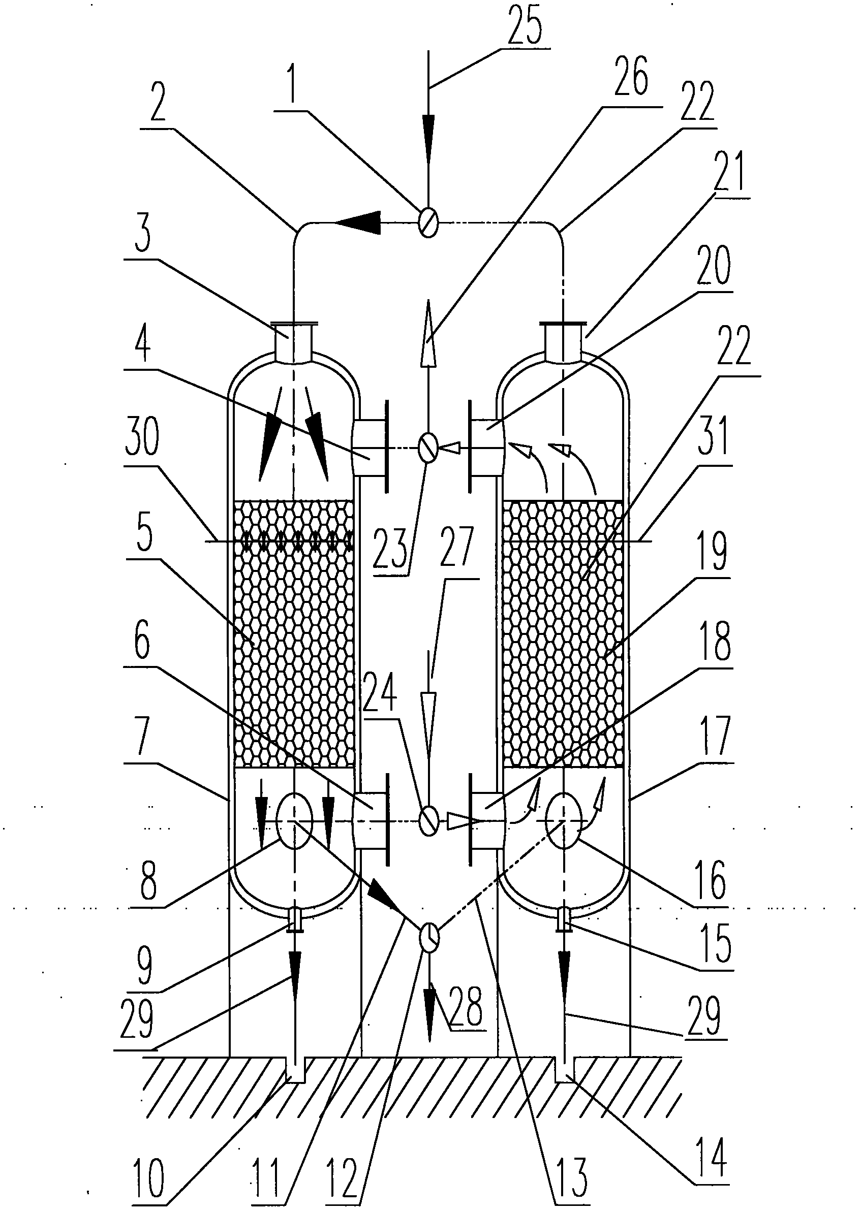
[0031] figure 1 It is a schematic diagram of state 1 of an air preheater of the present invention, heat storage chamber A stores heat, heat storage chamber B releases heat, and heat storage chamber 2 is composed of a shell 7, a three-way valve for hot flue gas 1, and flue gas from heat storage chamber A. Inlet 3, Regenerator A air outlet 4, Regenerator A heat storage medium 5 is a ceramic ball with a diameter of 15mm, Regenerator A air inlet 6, Regenerator A cold flue gas outlet 8, Regenerator A condensate outlet 9. Regenerator A condensate collection tank 10, regenerator A outlet flue 11 and cold flue gas three-way valve 12, regenerator A flue gas inlet 3 is set at the top of regenerator A, regenerator A The air outlet 4 is set at the upper part of the regenerator A, the air inlet 6 of the regenerator A is set at the lower part of the regenerator A, the cold flue gas outlet 8 of the regenerator A is set at the lower part of the regenerator A, and the condensate outlet of the ...


PUM


Abstract

The invention discloses an air preheater, which comprises at least two heat accumulation chambers, wherein hot flue gas inlets are formed in the heat accumulation chambers; the heat accumulation chambers are provided with condensed fluid and cold flue gas outlets; cold air inlets and hot air outlets are formed in the heat accumulation chambers; and heat accumulation media are filled in the heat accumulation chambers. According to the air preheater, the thermal efficiency of a heating furnace is improved to over 94 percent while the temperature of flue gas is reduced to be less than a dew point of acid; and simultaneously, acidic water, ash and other pollutants are recovered and condensed, so that the corrosion of equipment is delayed.

Description

technical field [0001] The invention relates to the technical field of flue gas waste heat recovery, in particular to a regenerative air preheater. Background technique [0002] Flame heating furnace is a process heating furnace widely used in petroleum refining, petrochemical, chemical and chemical fiber industries. It uses oil or gas as fuel, and the flame directly heats the fluid in the tube. At present, the exhaust gas temperature of the flame heating furnace is generally high, generally between 130°C and 180°C, and some may exceed 200°C, and the thermal efficiency is usually around 90%. There is still a large amount of physical sensible heat in the flue gas that cannot be used. More importantly, because the flue gas generated by the combustion of fuel oil and gas contains a large amount of water vapor, its latent heat of vaporization is discharged with the flue gas, causing a lot of energy waste. At the same time, SO in flue gas 2 , SO 3 , CO 2 , NOx and other harmf...

Claims


Application Information

Patent Timeline
Patent Type & Authority Applications(China)
IPC IPC(8): F23L15/00F28D20/00
CPCY02E60/142Y02E20/34Y02E60/14
Inventor 王德瑞
Owner CHINA PETROLEUM & CHEM CORP
Why Eureka
Try Eureka