
Infrared array focal plane read-out circuit

A readout circuit and infrared technology, applied in the field of circuits, can solve problems affecting the response rate of CTIA-type readout circuits, complex readout circuit design, and large volume of readout circuits, so as to improve time utilization and pixel response The effect of large rate and dynamic range

Inactive Publication Date: 2015-06-24
WUXI MENGSHE SENSING TECH
View PDF4 Cites 0 Cited by
  • Summary
  • Abstract
  • Description
  • Claims
  • Application Information

AI Technical Summary

Problems solved by technology

Among them, the CTIA-type readout structure has the advantages of good linearity, good uniformity, and large dynamic range, which are difficult to have in other structures, except that the circuit structure is relatively complicated and the power consumption is large, and it can also be connected with the correlated double sampling (CDS) circuit structure. , to eliminate the influence of reset noise and KTC noise, in addition, due to the non-uniformity of pixels and reference pixels, it also affects the response rate of CTIA-type readout circuits
[0005] The current readout method of the infrared focal plane mainly includes converting the detector signal first and then outputting the signal, or adopting a pipeline method, the detector signal conversion and signal output are carried out at the same time, the latter can make full use of time and have high efficiency, but the readout The circuit is often designed more complicated, resulting in a large readout circuit, large power consumption, and high cost

Method used


Image

  • Infrared array focal plane read-out circuit
  • Infrared array focal plane read-out circuit
  • Infrared array focal plane read-out circuit

Examples


Embodiment Construction

[0026] The present invention will be described in further detail below in conjunction with the accompanying drawings.

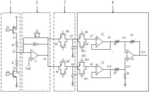
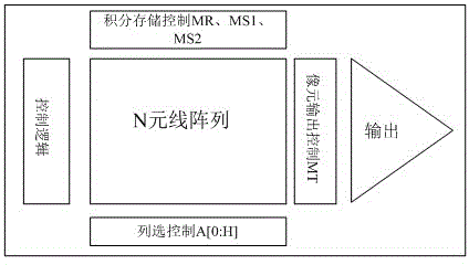
[0027] Such as figure 1As shown, the infrared column focal plane readout circuit of the present invention is composed of load resistance shunt circuit unit 1, integration / reset control circuit unit 2, storage circuit unit 3 and correlated double sampling CDS circuit unit 4. The load resistance shunt circuit unit 1 is composed of a pixel R1, a reference pixel Rf, a switch M1 and a switch M2, and is used for forming and outputting an integral current. The switching level is controlled by the voltage of the DA converter, which is used to solve the problem of excessive integration current due to the non-uniformity of the pixel and reference pixel when there is a TEC module, and by adjusting the pixel and reference pixel when there is no TEC module Bias to complete non-uniformity correction. The integral / reset control circuit unit 2 is composed of an operational...


PUM


Abstract

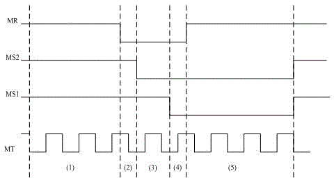
The invention discloses an infrared array focal plane read-out circuit which comprises a load resistor shunt circuit, a load switch control circuit, a capacitor transconductance feedback and amplifier circuit, an integral / resetting control unit circuit, a storage unit circuit, a correlated double-sampling circuit, an integral gating control circuit and a CDS (correlated double sampling) gating control circuit. The load switch control circuit is controlled by a DA (digital to analog) convertor, so that the problems that integral current is overheavy due to ununiformity of pixels and reference pixels and high resistance difference between the pixels and the reference pixels when a TEC (temperature controller) module is adopted. Complementary switches are used for weakening the charge injection effect. The level can be read out by a two-stage streamline scheme, wherein an integral control unit adopts a multi-way gating parallel integration storage manner, the CDS circuit adopts a one-way output manner, different pixel signals are sequentially output by controlling gating signals, integration and signal read-out can be carried out simultaneously by the two-stage streamline scheme, so that time utilization rate is increased, chip complexity is reduced and power consumption of chips is lowered.

Description

technical field [0001] The invention relates to a circuit. Specifically, it is an infrared column focal plane readout circuit in an infrared imaging system. Background technique [0002] With the development of science and technology, infrared imaging technology is becoming more and more mature, and it has been widely used in military, space technology, civilian and other aspects. The infrared focal plane array component is the core component of the infrared imager. The component is composed of an infrared detector array and a readout circuit (ROIC: Read-Out Integrated Circuits). The ROIC circuit is an important factor affecting the performance of the component. The design of the ROIC circuit has always been Towards low cost, low power consumption, high speed and high performance. [0003] Common ROIC circuits are composed of unit circuits, row and column gating circuits, logic sequence control circuits, and output buffer circuits. The basic functions realized by the u...

Claims


Application Information

Patent Timeline
Patent Type & Authority Patents(China)
IPC IPC(8): G01J5/02
Inventor 胡昊明赖建军
Owner WUXI MENGSHE SENSING TECH
Learn More