Infrared cut-off filter with blue glass

A technology of infrared cut-off and blue glass, which is applied in the field of optical filters, can solve the problems of reducing image quality, weakening the cut-off effect, and affecting image quality, and achieves the effects of uniform and clear color, overcoming color deviation, and reducing white fog phenomenon

Inactive Publication Date: 2012-12-05
晋谱(福建)光电科技有限公司
View PDF8 Cites 14 Cited by
  • Summary
  • Abstract
  • Description
  • Claims
  • Application Information

AI Technical Summary

Problems solved by technology

If this kind of oblique incident light is not effectively processed, it will greatly affect the transmittance of the visible spectrum, thereby affecting the imaging quality
[0003] Existing infrared cut-off filters are generally formed by stacking multi-layer films of high and low refractive index materials on the surface of transparent optical glass. The multi-beam interference principle of physical optics is used to cut off infrared light. When infrared rays pass through the multi-layer films, optical Interference destructive phenomenon, visible light passing through the multilayer film will produce interference constructive phenomenon, in order to realize the function of cutting off infrared light through visible light, and when the light is incident on the multilayer film at different angles, due to the equivalent optical thickness and equivalent refraction The rate changes, causing the entire spectrum to shift to the short-wave direction, generally around 27nm, causing part of the visible light to be filtered, so that the picture formed by the lens module has a large difference in the color surface of the center and edge parts, although the patent 200710202316.9 A method of stacking multiple film stacks is proposed, but although such a result achieves a small wavelength shift (16nm) under certain angle conditions, the total number of film layers at the price is very high, reaching 38-50 layers , the thickness of the film layer is large, the design and preparation are difficult, the cost is high, and it is not conducive to productization
[0004] Another method is to use a blue glass substrate. The infrared cutoff is based on the selective absorption of the incident light by the glass material itself, so as to achieve the infrared cutoff for the near-infrared 700-1200nm band light absorption, so there is no problem under the condition of large incident angle. Wavelength shift phenomenon, but the cut-off effect is strongly dependent on the thickness of the blue glass substrate. The thickness of the commonly used blue glass is 1.2mm, which can achieve a good infrared cut-off, but too thick thickness will also reduce the transmittance of the visible light part. , which is not conducive to the miniaturization of imaging devices
Modern camera products require smaller and smaller volumes, higher and higher requirements for image quality and color reproduction, and the infrared cut-off filter embedded in front of the CCD / CMOS image sensor generally requires a thickness of only 0.1mm-0.3 mm, the usual specifications are 0.1mm, 0.145mm, 0.21mm and 0.3mm. In such a thin substrate thickness space, if blue glass with the same thickness is used as the infrared cut filter, due to the thinner thickness, it is not suitable for the infrared band 700- The absorption of 1200nm is reduced, and the cut-off effect is weakened. As a result, when using 0.3mm thick blue glass, the cut-off characteristic of the infrared band can only reach about 20% transmittance, which is far lower than the requirement that the infrared cut-off transmittance of high-pixel cameras should be less than 0.5%.
[0005] Under the increasingly higher pixel requirements of mobile phone cameras, the problems existing in the existing infrared cut filter will inevitably affect the normal imaging effect and reduce the imaging quality

Method used


Image

  • Infrared cut-off filter with blue glass
  • Infrared cut-off filter with blue glass
  • Infrared cut-off filter with blue glass

Examples


Embodiment Construction

[0023] In order to describe the technical content, structural features, achieved goals and effects of the present invention in detail, the following will be described in detail in conjunction with the embodiments and accompanying drawings.

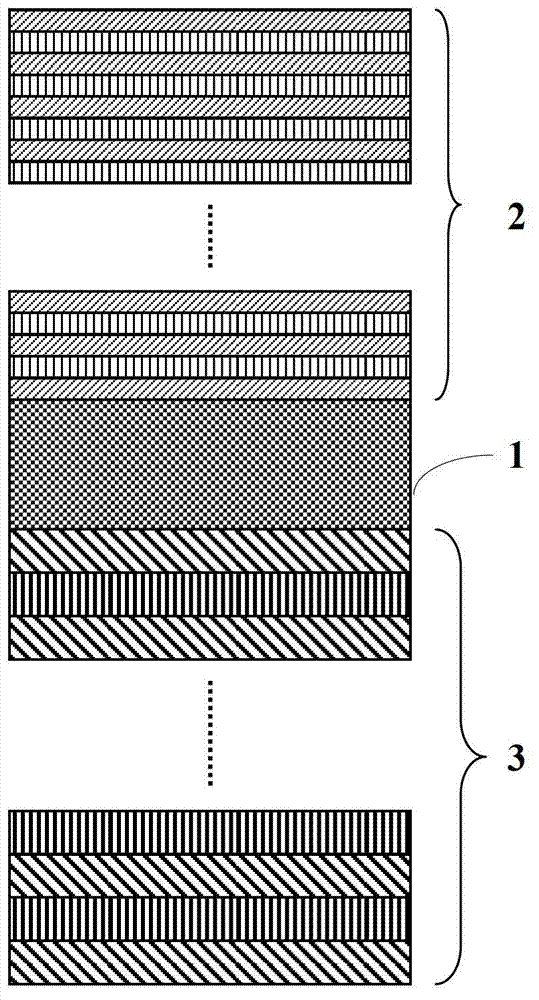
[0024] The composite thin-film blue glass infrared cut-off filter of the present invention comprises a substrate, an infrared short-wave cut-off film stack 2 is arranged on the front surface of the substrate, and an infrared long-wave cut-off film stack 3 is arranged on the rear surface of the substrate, wherein the substrate material is blue glass, and the thickness is between Between 0.1mm-0.55mm, the commonly used specifications are 0.1mm, 0.145mm, 0.21mm, 0.3mm, 0.45mm and 0.55mm. The infrared short-wave cut-off film stack and the infrared long-wave cut-off film stack 3 are respectively stacked alternately by thin films of high and low refractive index materials, wherein the high refractive index material is TiO 2 、 Ta 2 o 5 , Nb 2 ...


PUM

PropertyMeasurementUnit
thicknessaaaaaaaaaa
thicknessaaaaaaaaaa
thicknessaaaaaaaaaa

Abstract

The invention discloses an infrared cut-off filter with blue glass. The infrared cut-off filter comprises a substrate. The substrate is made of the blue glass, an infrared short-wave cut-off membrane stack is arranged on the front surface of the substrate, an infrared long-wave cut-off membrane stack is arranged on the rear surface of the substrate, and membranes made of high-refractive-index materials and membranes made of low-refractive-index materials are stacked alternately to form the infrared short-wave cut-off membrane stack and the infrared long-wave cut-off membrane stack. The two infrared cut-off membrane stacks with few membrane layers are combined with the blue glass, and the requirement on the high cut-off characteristic in an infrared spectrum interval ranging from 700 nanometers to 1100 nanometers is met by the infrared absorbing characteristic of the blue glass and the infrared reflection characteristic of the cut-off membrane stacks jointly under the condition that the substrate made of the blue glass is ultra-thin.

Description

technical field [0001] The invention relates to an optical filter, in particular to a composite film-type blue glass infrared cut-off filter for a high-pixel camera. Background technique [0002] With the development of high-end smart phones, especially the hot sales of Apple mobile phones, the requirements for mobile phone cameras are getting higher and higher, which has grown from the initial 1.3 million pixels to 5 million pixels or even 8 million pixels. In the future, mobile phones with 8 million pixels and above Cameras will become standard on smartphones. In the mobile phone camera, the infrared cut-off filter located in front of the image sensor CCD or CMOS effectively filters the infrared rays through the visible light, thereby producing normal color images, which is a key component in the camera. With the continuous improvement of imaging pixels, higher and higher requirements are put forward for infrared cut filters in terms of clear imaging, true color reproduct...

Claims


Application Information

Patent Timeline
Patent Type & Authority Applications(China)
IPC IPC(8): G02B5/26B32B9/04
Inventor 卜轶坤关振奋吴冠伟张慎兴
Owner 晋谱(福建)光电科技有限公司
Why Eureka
Try Eureka