Optical pickup device

An optical pickup and optical element technology, which is applied in the manufacture of beam guiding devices, instruments, optical heads, etc., can solve the problems of decreased bonding strength, low elastic modulus, unsuitable for optical elements, etc., and achieves high position accuracy, bonding Effects that do not drop in strength

Inactive Publication Date: 2012-12-05
HITACHI MEDIA ELECTORONICS CO LTD
View PDF9 Cites 0 Cited by
  • Summary
  • Abstract
  • Description
  • Claims
  • Application Information

AI Technical Summary

Problems solved by technology

[0009] In addition, in Patent Document 1, in order to suppress the misalignment of the optical components, when an adhesive having a high elastic modulus such as that used for bonding optical elements is used in the optical pickup device, the adhesive is in contact with the optical pickup case. The bonded interface has a high possibility of delamination, especially when stress caused by long-term environmental changes is applied, and it can be expected that the bond strength will decrease
In addition, if the elastic modulus is low, it will become soft and easily cause positional deviation, so it is not suitable for bonding optical elements
[0010] In addition, in Patent Document 2, the application position of the adhesive cannot be controlled.

Method used


Image

  • Optical pickup device
  • Optical pickup device
  • Optical pickup device

Examples


Embodiment 1

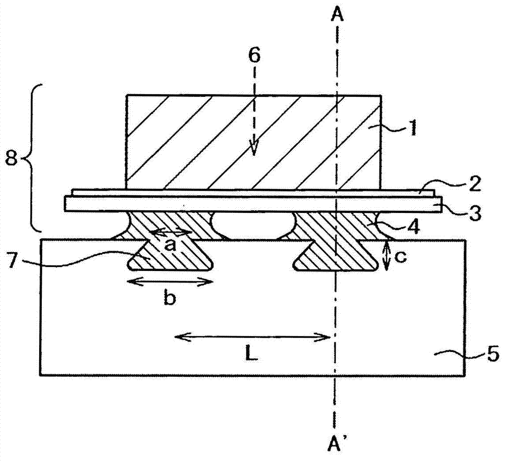
[0027] use Figure 1 ~ Figure 4 A first embodiment of the present invention will be described. First, use Figure 4 The configuration of the optical pickup device will be described. In addition, in this embodiment, the light-receiving element is used as an example for description, but it can also be applied to other light elements such as light-emitting elements. Figure 4 It is a schematic overall configuration diagram when optical components that function as optical lenses, such as an optical component unit 8 , a grating lens 11 , a coupling lens 12 , and a detection lens 13 , are bonded and fixed to the optical pickup case 5 . The optical component assembly 8 and various lenses move in the direction of the arrow in the downward direction, and are arranged at a prescribed position with respect to the optical axis of the optical pickup box 5. 8, the front or back side parallel to the optical axis is bonded and fixed. In addition, reference numeral 100 represents the confi...

Embodiment 2

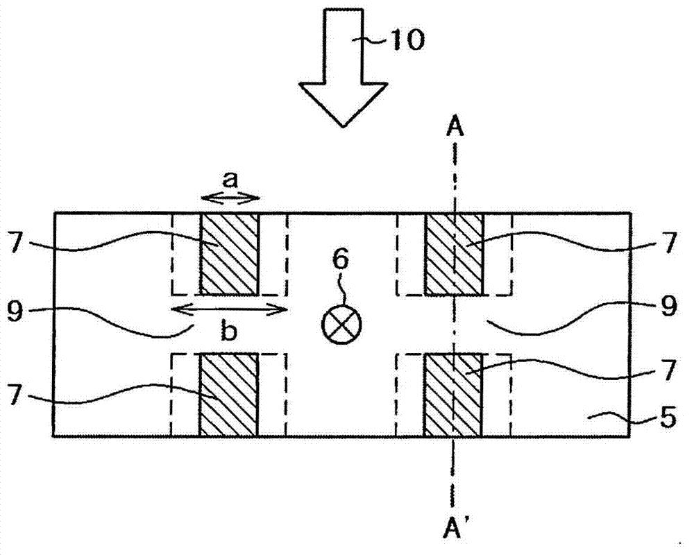
[0042] use Figure 5 (a), (b) The 2nd Example is demonstrated. In addition, matters described in the first embodiment but not described in the present embodiment can also be applied to the present embodiment unless otherwise specified. Figure 5 (a) and (b) are plan views of the bonding portion between the optical component unit 8 and the optical pickup case 5 in the optical pickup device of the present embodiment. The optical component unit is composed of a flexible printed circuit board 2 connected to the light receiving element 1 and a reinforcing plate 3 supporting the flexible printed circuit board 2 .

[0043] In the groove portion on the side of the optical pickup box, the relationship between the opening length a of the groove portion 7 and the longest length b inside the groove is a bonding structure of a

Embodiment 3

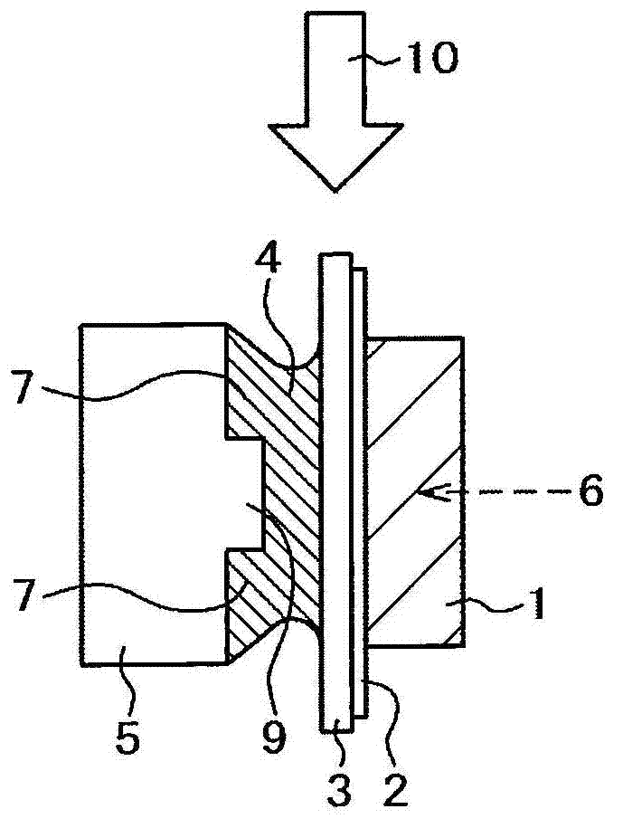
[0048] use Figure 6 (a), (b) The third embodiment will be described. In addition, matters described in Embodiment 1 or Embodiment 2 but not described in this embodiment can be applied to this embodiment unless otherwise specified. Figure 6 (a) and (b) are side views of the optical pickup case of the optical pickup device of this embodiment. Figure 6 (a) is an example in which, when bonding the back surface of the optical component unit, one groove portion is used as the bonding and fixing portion.

[0049] Figure 6 (b) In the case of bonding the back of the optical component unit, two grooves are provided as bonding and fixing parts, one groove for the optical pickup box is provided on the upper and lower sides, and the arrangement is arranged. An example of a sawtooth structure.


PUM


Abstract

An optical pickup device, which is capable of inhibiting peeling from a bonded interface and deviation of an optical axis from being caused even by long-term environmental variations, has a photonic device (1), a flexible printed substrate (2), a holding member (3), an optical pickup case (5) and a bonding connection (4) for bonding the holding member (3) and the optical pickup case (5) together. The adhesive enters an inside of the optical pickup case. The adhesive has a cross-sectional area on the outer surface of the optical pickup case in communication with the inside smaller than a cross-sectional area in the inside of the optical pickup case.

Description

technical field [0001] The present invention relates to an optical pickup device for recording and reproducing optical recording media such as CD (Compact Disc), DVD (Digital Versatile Disc) or BD (Blu-ray Disc). Background technique [0002] An optical pickup device for recording and reproducing optical recording media such as CD, DVD, or BD, or an optical disk drive device incorporating an optical pickup device includes: passing the outgoing light from a light emitting element such as a laser diode through various lenses and prisms, reflecting An optical system that guides the objective lens, such as mirrors, and converges on the optical recording medium; and uses a photoelectric system for making the return light from the optical recording medium pass through the objective lens and other various lenses, prisms, and mirrors and converting the light output into an electrical signal Optical system that converts light received by the element. Among them, in the bonding and f...

Claims


Application Information

Patent Timeline
Patent Type & Authority Applications(China)
IPC IPC(8): G11B7/135
CPCG11B7/135G11B7/13G11B7/12G11B7/22
Inventor 野村里佳盛山武纪
Owner HITACHI MEDIA ELECTORONICS CO LTD
Why Eureka
Try Eureka