
Hydrostatic hybrid drive system

A drive system and hybrid technology, applied in hybrid vehicles, fluid hybrid vehicles, pneumatic power devices, etc., can solve problems such as reducing the driving power of internal combustion engines, and achieve the effect of compensating for compression loss

Active Publication Date: 2012-12-05
HYDAC TECH GMBH
View PDF7 Cites 12 Cited by
  • Summary
  • Abstract
  • Description
  • Claims
  • Application Information

AI Technical Summary

Problems solved by technology

This opens up the possibility of reducing the drive power of the internal combustion engine used as primary drive for a comparable driving power

Method used


Image

  • Hydrostatic hybrid drive system
  • Hydrostatic hybrid drive system
  • Hydrostatic hybrid drive system

Examples


Embodiment Construction

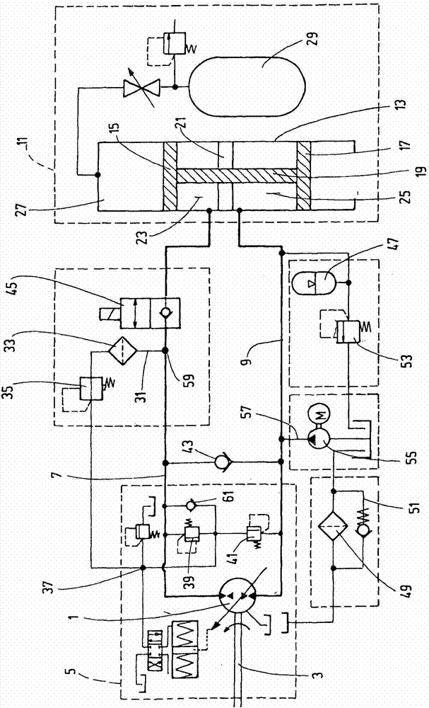
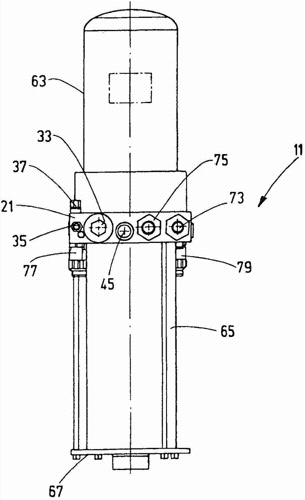
[0019] figure 1 A hydraulic circuit diagram of an exemplary embodiment is shown, in which a pump-motor unit is marked with 1, which is driven in a constant direction of rotation by the internal combustion engine of the relevant vehicle, which, like the rest of the vehicle components, is not shown . In the present example, the pump-motor unit 1 is directly driven by a schematically represented crankshaft 3 of an internal combustion engine. The pump-motor unit 1 is an axial piston machine whose swivel angle is adjustable in both swivel directions beyond a neutral zero position by means of an electrohydraulic control unit 5 so that the pump-motor unit 1 It is possible to work both in pump operation and in motor operation while maintaining a constant direction of rotation. The control unit 5 interacts via an interface (not shown) with the electronic engine management system of the vehicle corresponding to the prior art.

[0020] A first working line 7 is connected to the high-p...


PUM


Abstract

The invention relates to an hydrostatic hybrid drive system for road vehicles, said system comprising a pump / motor unit (1) which is or can be connected to the powertrain of the vehicle, can be controlled by means of a control unit (5) in a pump or motor operation and can be connected to a high-pressure hydraulic accumulator via a first working line (7) that can be closed by means of a control valve (45) and to a low-pressure hydraulic accumulator via a second working line (9). The high-pressure hydraulic accumulator and low-pressure hydraulic accumulator are formed by a double-piston accumulator (11), in which a high-pressure side and a low-pressure side having respective accumulator pistons (15, 17) are formed in an accumulator housing (13), wherein the fluid chambers (23 and 25) of the high-pressure side and the low-pressure side are separated by a central housing part (21) through which the common piston rod for both accumulator pistons (15, 17) extends. The invention is characterised in that the control unit (5) of the pump / motor unit (1) having a control area can be supplied from the first working line (7) via a line connection (59) which is provided on the first working line (7) between the pump / motor unit (1) and the control valve (45).

Description

technical field [0001] The invention relates to a hydrostatic hybrid drive system for road vehicles, comprising a pump-motor unit connected or connectable to the drive train of the vehicle, which pump-motor unit can be controlled by means of a control unit Pump operation or motor operation is controlled and can be connected to the high-pressure hydraulic accumulator via the first working line which can be blocked by the control valve and can be connected to the low-pressure hydraulic accumulator via the second working line, wherein the high-pressure hydraulic accumulator The accumulator and the low-pressure hydraulic accumulator are formed by a double-piston accumulator in which the high-pressure side and the low-pressure side are formed by one accumulator piston each in an accumulator housing, wherein , the high-pressure-side and low-pressure-side fluid chambers are separated by a housing intermediate part, through which the piston rod common to the two accumulator pistons ex...

Claims


Application Information

Patent Timeline
Patent Type & Authority Applications(China)
IPC IPC(8): B60K6/12F15B1/22F15B1/24F15B1/033F15B1/14F16H61/433
CPCF15B2201/32B60K6/12F15B1/024F15B2211/20569F15B2201/205F16H61/433F15B2201/31F15B2211/212F15B2211/20561Y02T10/6208Y02T10/62
Inventor F·鲍尔H·巴尔特斯P·克洛夫特
Owner HYDAC TECH GMBH
Learn More