Method and device for pressure amplification in cylinders, in particular hydraulic rams

Inactive Publication Date: 2008-09-16
VOSS WOLFGANG
View PDF7 Cites 3 Cited by
  • Summary
  • Abstract
  • Description
  • Claims
  • Application Information

AI Technical Summary

Benefits of technology

[0006]This method hence makes it possible to increase the pressure level within the piston surface cavity in a specific manner, regardless of the starting point of the pressure level of the pressure transducer, so as to achieve advantages. When for example proceeding from a pressure level that is clearly below 400 bar, the method according to the invention allows the pressure level in the cylinder to be increased in a specific manner without requiring other lines, a cylinder with different dimensions or another pump. Rather the pressure within the cylinder is increased such that the desired maximum pressure level is reached. This way for example in underground mining and tunnel construction, the necessary input pressure in the stamp, i.e. the appropriately designed cylinder, can be achieved without requiring the use of an expensive high pressure pump, which also accordingly requires special lines and valves. Rather, a less expensive and simpler high pressure pump reaching a correspondingly lower pressure level can be used in order to still attain the desired pressure level inside the cyl

Problems solved by technology

Due to various circumstances, however, it is not always guaranteed that the afore-mentioned pressure is available in the piston surface cavity, so so-called adjustment circuits are known in underground mining and tunnel construction which allow the volume in the piston surface cavity to be adjusted through

Method used


Image

  • Method and device for pressure amplification in cylinders, in particular hydraulic rams
  • Method and device for pressure amplification in cylinders, in particular hydraulic rams
  • Method and device for pressure amplification in cylinders, in particular hydraulic rams

Examples


Example

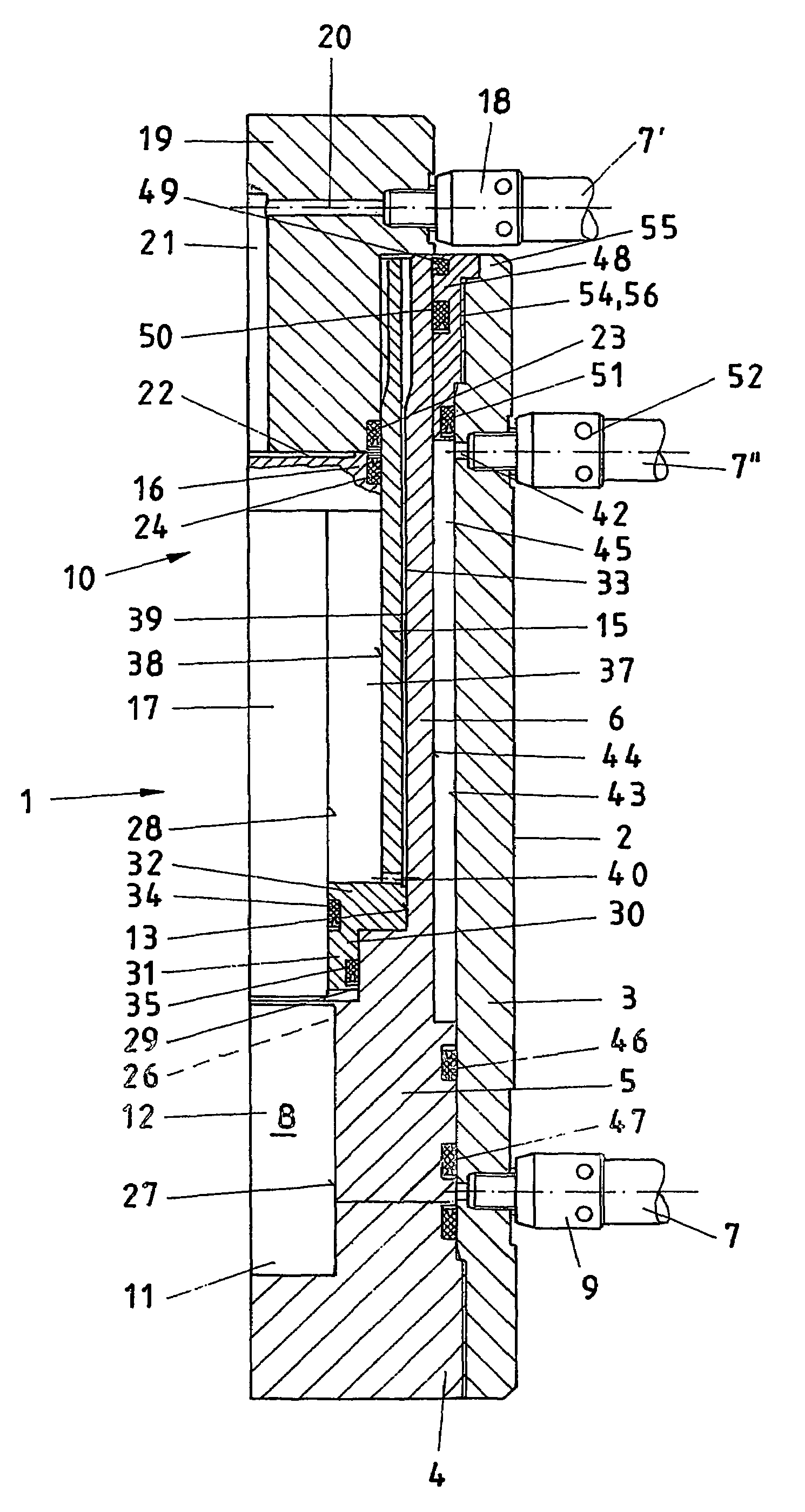
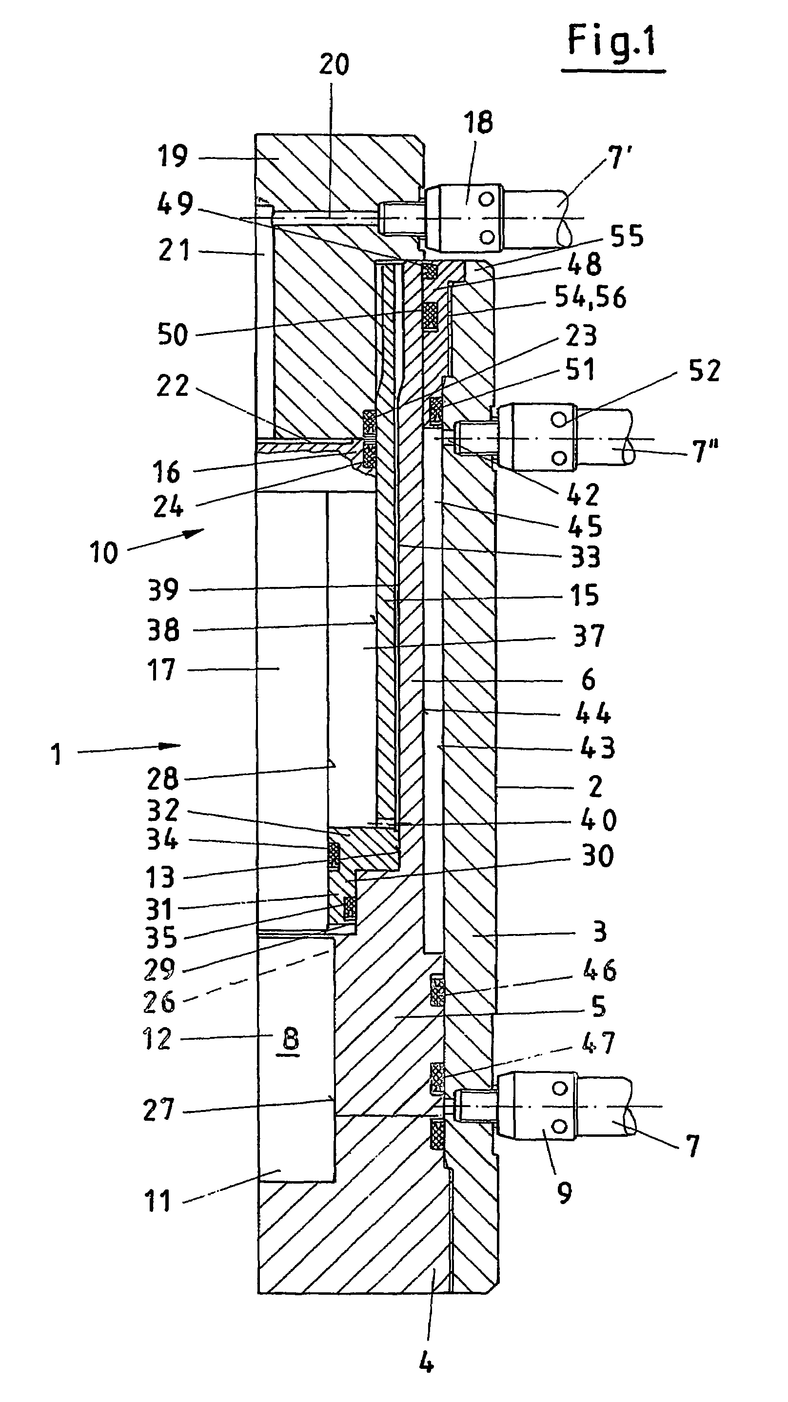
[0030]FIG. 1 shows a cylinder 1 in the longitudinal section, whereby it becomes clear that the foundation 2 of this cylinder 1 comprises a cylinder housing 3 with a cylinder cover 4 and a piston 5 with a piston rod 6. The piston 5 with the piston rod 6 is arranged displaceably inside the cylinder housing 3, with the supply line 7 feeding hydraulic fluid or pressure transducer into a piston surface cavity 8 via an input valve 9. This pressure transducer penetrating into the piston surface cavity 8 ensures that the piston 5 with the piston rod 6 and the rod head 19 at the end travels out of the cylinder housing 3. The inside, here referred to as a compressor 10, does not impair this movement and / or supports it.

[0031]The piston surface cavity 8 in the illustrated example is formed by the borehole 11 in the cylinder cover 4, the borehole 12 in the piston 5 and the borehole 13 in the piston rod 6. The piston surface cavity 8 hence has the shape of a cylinder.

[0032]The large piston rod 6 ...


PUM


Abstract

A method and corresponding cylinder for pressure amplification in cylinders are disclosed. A second pressurizing piston with a small piston rod is arranged within the cylinder, in other words, within the cylinder housing, by means of which the piston surface cavity in the vicinity of the piston or the pressure medium present there can be further compressed. It is thus possible to increase the stroke displacement where required or to increase the pressure within the cylinder. Further advantages can also be achieved with the above.

Description

[0001]This application claims the benefit of German Application No. 103 06 128.2 filed Feb. 14, 2003 and PCT / DE2004 / 000207, which are hereby incorporated by reference in their entirety.BACKGROUND OF THE INVENTION.[0002]The invention relates to a method for increasing pressure in cylinders used for oil hydraulic, water hydraulic, emulsion hydraulic as well as plasma and other fluid hydraulic systems, in which two part or multi-part cylinders are moved apart or together in a controlled fashion by means of valves, and the introduced pressure transducer, which has passed a high pressure pump, whereby in the piston surface cavity beneath the respective piston a specified pressure, even after separation from one another, is generated and maintained through compression of the piston surface cavity. The invention moreover relates to a cylinder for performing the method, comprising a foundation with cylinder housing, the body being connected to a high pressure pump via a supply line, as well...

Claims


Application Information

Patent Timeline
IPC IPC(8): F15B11/00B30B15/16E02F9/22E21D23/16F15B3/00F15B11/032
CPCE02F9/22E21D23/16F15B11/0325F15B3/00F15B2211/7055F15B2211/214
Inventor VOSS, WOLFGANG
Owner VOSS WOLFGANG
Why Eureka
Try Eureka