Solid carbide drill chip breaker groove for steel part and design method thereof

A solid carbide and design method technology, applied in metal processing equipment, drilling/drilling equipment, twist drills, etc., can solve problems such as unfavorable chip removal, cutting entanglement, and large cutting heat, so as to reduce temperature and prevent The effect of winding and improving durability

Inactive Publication Date: 2012-12-12
TAIZHOU X DAKE CUTTING TOOL
View PDF6 Cites 6 Cited by
  • Summary
  • Abstract
  • Description
  • Claims
  • Application Information

AI Technical Summary

Problems solved by technology

At the same time, the cutting steel parts should form curling chips, otherwise the cutting will be wound on the tool handle and tool of the machine tool, which will affect the next step of processing
In addition, the curly cutting must be able to break naturally under the length control requirements, otherwise, the chips are too long, increasing the friction with the inner wall of the hole, increasing the resistance, forming chip blocking, and forming extrusion piles with the chips formed at the moment of cutting, causing blockage The cutting tool is broken and broken; if the chip volume radius is too small, which greatly exceeds the yield strength of its material, it will cause cutting force, excessive cutting heat, and premature cutting curl and bending, breaking, which is also unfavorable for chip removal

Method used


Image

  • Solid carbide drill chip breaker groove for steel part and design method thereof
  • Solid carbide drill chip breaker groove for steel part and design method thereof
  • Solid carbide drill chip breaker groove for steel part and design method thereof

Examples


Embodiment

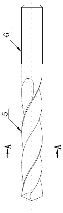
[0023] The design method for the chip breaker of solid carbide drill bits for steel parts includes the following process steps:

[0024] 1. The selection of five-axis grinding center equipment is the necessary equipment for making carbide tools;

[0025] 2. The grinding wheel is made of diamond grinding wheel, the type of grinding wheel is 1V1 (75°);

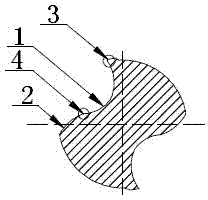
[0026] The following are the specific parameters of the chip breaker cross section R of the drill bit that should be achieved for chip rolling and chip breaking. The specific parameters are as follows:

[0027] Blade size Groove bottom radius Blade size Groove bottom radius Φ3 R1.23 Φ4 R1.45 Φ5 R1.71 Φ6 R2.02 Φ7 R2.31 Φ8 R2.6 Φ9 R2.89 Φ10 R2.99 Φ11 R3.25 Φ12 R3.41 Φ13 R3.61 Φ14 R3.81 Φ15 R4.06 Φ16 R4.1 Φ17 R4.18 Φ18 R4.25 Φ19 R4.42 Φ20 R4.6 Φ21 R4.68 Φ22 R4.75 Φ23 R4.9 Φ24 R5.1 Φ25 R5.41

[0028] Th...


PUM


Abstract

The invention discloses a solid carbide drill chip breaker groove for a steel part and a design method of the solid carbide drill chip breaker groove for the steel part. The structure of the solid carbide drill chip breaker groove for the steel part is as follows: one end of a chip rolling groove is a negative chamfered edge, the other end thereof is a chip breaker table, and the chip rolling groove is arranged at a joint point of the chip breaker table R. The design method of the solid carbide drill chip breaker groove for the steel part comprises the following steps of: 1, selecting a five-axis grinding centric device; 2, selecting a diamond grinding wheel in a type of 75 degrees as a grinding wheel; and 3, carrying out the specific operation as follows: 1) adopting an imported five-axis-linked grinding center, and setting a cutting blade-blade angle of inclination in a machining center program; 2) setting the thickness of a drill core according to 26% of diameter of the drill of the steel part; and 3) enabling a solid carbide drill of phi(10) to have the following specific parameters of chip rolling and chip breaking requirements: a front angle is 10 degrees, the thickness of the core is 2.5 mm, a tilt angle is 8 degrees and an angle of declination of the grinding wheel is 3 degrees. The solid carbide drill chip breaker groove for the steel part has the following advantages that: the temperature of a cut region is lowered, the durability of a cutting tool is improved, the winding of cut chips on a cutter handle and the cutting tool are effectively avoided, the chip blocking is avoided, the breaking phenomenon of the cutting tool, caused by the chip blocking, is eliminated, the high-speed cutting is completely adapted, and the cutting requirement of high-strength steel is met.

Description

technical field [0001] The invention relates to a solid carbide drill chip breaker for steel parts and a design method thereof. Background technique [0002] The general method of making drill bits in our country is to select the corresponding special groove milling cutter according to the diameter of the groove of the drill bit. The country has standards in this regard. Ordinary high-speed steel drills have slow speed and small feed rate, and the deep holes are processed by pecking, and they must be driven into a section to exit chip removal. This can basically solve the problem of chip curling and chip removal, and it has been used to this day. Solid carbide drills are used on CNC machine tools. Its characteristics are: high speed, large feed rate, and chips are generated in an instant. It is required to remove chips quickly, timely and smoothly, especially when cutting steel materials. The cutting force is large, A large amount of cutting heat is generated. In addition t...

Claims


Application Information

Patent Timeline
Patent Type & Authority Applications(China)
IPC IPC(8): B23B51/02B24B3/24
Inventor 王伟
Owner TAIZHOU X DAKE CUTTING TOOL
Why Eureka
Try Eureka