Ultra-high frequency (UHF) radio frequency identification (RFID) reader-writer antenna

A radio frequency identification and ultra-high frequency technology, applied in the field of radio frequency identification RFID reader antenna, can solve the problems of small antenna coverage angle, inability to achieve uniform coverage, insufficient reading distance, etc., achieve accurate automatic identification function, and be popularized and applied foreground effect

Active Publication Date: 2012-12-12
北京测态培元科技有限公司
View PDF4 Cites 5 Cited by
  • Summary
  • Abstract
  • Description
  • Claims
  • Application Information

AI Technical Summary

Problems solved by technology

However, since this type of antenna uses near-field magnetic coupling, its reading distance is not enough, which also limits its application range
[0005] In this way, when a longer reading distance is required, the existing technology uses the far-field antenna mode; however, the coverage angle of this type of antenna is small, and uniform coverage cannot be achieved
When an area with a uniform field distribution is required, the near-field RFID reader antenna mode is mostly used at present, but its disadvantage is that its reading distance is small

Method used


Image

  • Ultra-high frequency (UHF) radio frequency identification (RFID) reader-writer antenna
  • Ultra-high frequency (UHF) radio frequency identification (RFID) reader-writer antenna
  • Ultra-high frequency (UHF) radio frequency identification (RFID) reader-writer antenna

Examples


Embodiment Construction

[0015] In order to make the object, technical solution and advantages of the present invention clearer, the present invention will be further described in detail below in conjunction with the accompanying drawings and embodiments.

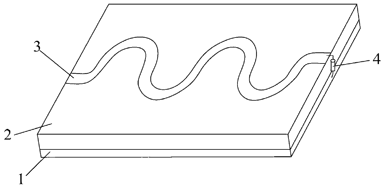
[0016] The radio frequency identification RFID reader antenna of the ultra-high frequency UHF of the present invention is made up of upper and lower conductive layers made of metal materials and an insulating material medium layer between the upper and lower layers, wherein the lower floor is Rectangular pure copper plate, the upper layer is an antenna composed of a traveling wave-shaped pure copper feeder laid on the upper surface of the insulating material dielectric layer; in order to enable the antenna to cover each polarization direction and fully cover the entire antenna area, the traveling wave of the antenna There are no specific requirements and restrictions on the shape or size. Traveling waves including sine wave, cosine wave, triangle wa...


PUM

PropertyMeasurementUnit
thicknessaaaaaaaaaa

Abstract

The invention discloses an ultra-high frequency (UHF) radio frequency identification (RFID) reader-writer antenna. The UHF RFID reader-writer antenna consists of an upper metal material conductive layer, a lower metal material conductive layer and an insulating material medium layer positioned between the upper metal material conductive layer and the lower metal material conductive layer, wherein a lower bottom plate is a rectangular pure copper plate; the upper layer is a traveling wave-shaped antenna formed by a pure copper feeder line which is laid on the upper surface of the insulating material medium layer; in order to cover all polarization directions and fully cover the area of the overall antenna, the traveling wave shape of the antenna is required to be not less than a period; moreover, the leftmost side of the antenna is connected with a feed power supply; the tail end of the rightmost side of the antenna is connected with the lower bottom plate through a matching resistor; and the width of the feed line of the antenna and the resistance of the matching resistor both depend on the structural shape of the overall antenna: namely the lengths, the widths and the thicknesses of the upper conductive layer, the lower conductive layer and the intermediate insulating material medium layer, and the dielectric coefficient of the medium material. The antenna has large coverage and long reading distance; and a plurality of tags can also be read effectively when passing through at a high speed. Moreover, the structure is simple; and the project is easy to implement and low in cost.

Description

technical field [0001] The invention relates to a radio frequency identification (RFID) reader-writer antenna working on ultra-high frequency UHF, and belongs to the technical field of wireless communication antennas. Background technique [0002] Radio Frequency Identification (RFID) technology is an automatic identification technology that began to emerge in the 1990s. The theoretical basis of radio frequency identification technology was laid by "Communication Using Reflected Power" published by Harry Stockman in 1948. . It is a technology that uses radio frequency signals to achieve non-contact information transmission through spatial coupling (alternating magnetic field or electromagnetic field), and to identify the target object through the transmitted information. The working principle of radio frequency identification technology in the low frequency band is based on the transformer coupling model, that is, the energy transfer and signal transmission between the prim...

Claims


Application Information

Patent Timeline
Patent Type & Authority Applications(China)
IPC IPC(8): H01Q1/38
Inventor 陈晓东俞俊生姚远
Owner 北京测态培元科技有限公司
Why Eureka
Try Eureka