High-speed permanent magnetic wind driven generator rotor sheet

A wind turbine, rotor punching technology, applied in the direction of magnetic circuit rotating parts, magnetic circuit shape/style/structure, etc., can solve the problems of complex manufacturing and assembly processes, reducing the reliability of rotor structure, and difficulty in rotor ventilation and heat dissipation. , to achieve the effect of easy processing and manufacturing, improving anti-demagnetization ability and avoiding deformation

Inactive Publication Date: 2012-12-12
HARBIN ELECTRIC MASCH CO LTD
View PDF2 Cites 9 Cited by
  • Summary
  • Abstract
  • Description
  • Claims
  • Application Information

AI Technical Summary

Problems solved by technology

The manufacturing and assembly process of this rotor structure is complicated, and the centrifugal force will cause large deformation of the rotor magnetic poles during high-speed operation, and stress concentration is likely to occur at the tail of the rotor magnetic pole T, which reduces the reliability of the

Method used


Image

  • High-speed permanent magnetic wind driven generator rotor sheet
  • High-speed permanent magnetic wind driven generator rotor sheet
  • High-speed permanent magnetic wind driven generator rotor sheet

Examples


Embodiment Construction

[0019] The specific embodiments of the present invention will be further described below in conjunction with the accompanying drawings.

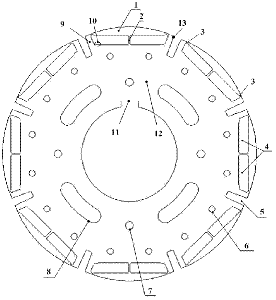
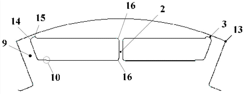
[0020] Such as figure 1 As shown, the present invention is a high-speed permanent-magnet wind-driven generator rotor punch applied to a high-speed permanent-magnet wind-driven generator, and the example is an 8-pole structure. The rotor punching piece is in the form of a full circle punching piece. Each rotor magnetic pole 13 has two symmetrical permanent magnet slots 4, which are separated by the middle magnetic bridge 2. The outer circle of the rotor magnetic pole 13 is an eccentric arc; The magnetization directions of the permanent magnets installed in the slot 4 are the same, and the magnetization directions of adjacent magnetic poles are opposite. Each permanent magnet slot is provided with an installation positioning step 10 toward the bottom of the slot inside the rotor punching plate; between two adjacent rotor poles, there is a The...


PUM


Abstract

The invention relates to a high-speed permanent magnetic wind driven generator rotor sheet, wherein a permanent magnet groove below each rotor magnetic pole is of a double section symmetrical structure which is isolated by an intermediate magnetic bridge; an axial ventilation slot is formed between the adjacent two magnetic poles; and the excircle of the rotor magnetic pole is an eccentric circular arc, the permanent magnet groove is provided with a permanent magnet mounting and locating step, tightening screw vents, lamination location holes and waist-shaped lightening holes are uniformly distributed in the rotor sheet, and a keyway is formed in the inner circle of the rotor sheet. After the integral round rotor sheet is adopted, a rotor has a simpler structure, a permanent magnet is not needed to be fixed through other measures, and the rotor sheet is easy to process and produce; the intermediate magnetic bridge can be used for effectively improving the rotor strength, and accordingly, the operation reliability of the rotor is improved; the eccentric circular arc of the rotor magnetic pole and the structural parameters of the magnetic bridge are adjusted, the output performance of a generator can be effectively improved, and the anti-demagnetizing performance of a motor is improved under the short circuit condition; and the ventilation slot is formed between the rotor poles, so the ventilation and heat dissipation capabilities of the whole generator can be effectively improved.

Description

technical field [0001] The invention relates to a high-speed permanent magnet wind power generator rotor stamping. Background technique [0002] At present, high-speed permanent magnet wind turbines are being used more and more because of their small size, light weight, and high efficiency. The rotor structure of high-speed permanent magnet wind turbine mainly has two forms: surface mount type and built-in type. In the surface-mounted structure, the permanent magnet poles are usually fixed by inter-pole compression. Under the action of electromagnetic force, centrifugal force and other factors, the fastening parts are easy to loosen or even fall off, which will bring serious failures to the safe operation of the generator. Hidden danger. Moreover, in the case of a short circuit, the permanent magnet is prone to local loss of magnetism, which seriously degrades the performance of the generator. In the built-in structure, the rotor magnetic pole adopts the hanging pole form...

Claims


Application Information

Patent Timeline
IPC IPC(8): H02K1/27H02K1/32
Inventor 宫海龙孙玉田李明哲王亮张艳竹赵玉吉高钰阁盛杉许善椿
Owner HARBIN ELECTRIC MASCH CO LTD
Why Eureka
Try Eureka