Helical electromagnetic stirring device

A technology of spiral electromagnetic stirring and electromagnetic induction, which is applied in the field of electromagnetic casting and electromagnetic processing of materials, can solve the problems of limited spiral stirring effect and unfavorable spiral stirring

Active Publication Date: 2012-12-19
ANGANG STEEL CO LTD
View PDF9 Cites 12 Cited by
  • Summary
  • Abstract
  • Description
  • Claims
  • Application Information

AI Technical Summary

Problems solved by technology

Stacking multiple rotating magnetic field generators up and down together, according to the principle of electromagnetic fluid mechanics, will generate vertical traveling wave force in the metal melt, but it is affected by the number of yoke arrangements on the vertical section and the continuity of the yoke back , the magnitude of this force will be much smaller than the circumferential rotational force, so the spiral stirring effect will be limited
Similarly, with the helical agitation formed by the traveling wave magnetic field juxtaposed in the circumferential direction, the rotational force in the circumferential direction will be much lower than the traveling wave force in the circumferential direction, which is not conducive to effective helical agitation

Method used


Image

  • Helical electromagnetic stirring device
  • Helical electromagnetic stirring device
  • Helical electromagnetic stirring device

Examples


Embodiment 1

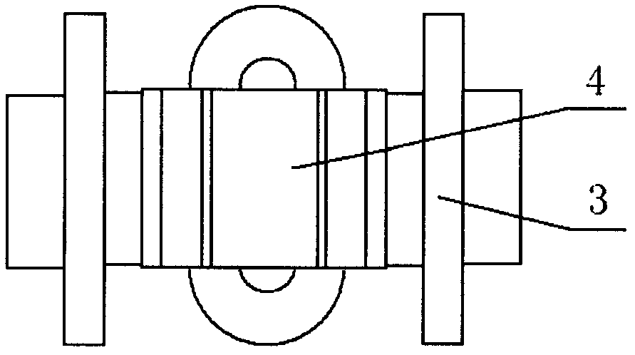
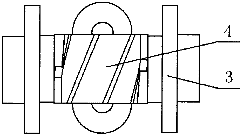
[0023] Embodiment 1: as image 3 and 4 As shown, it is suitable for the spiral electromagnetic stirring device where the billet is round billet or square billet.

[0024] 1. Electromagnetic induction system

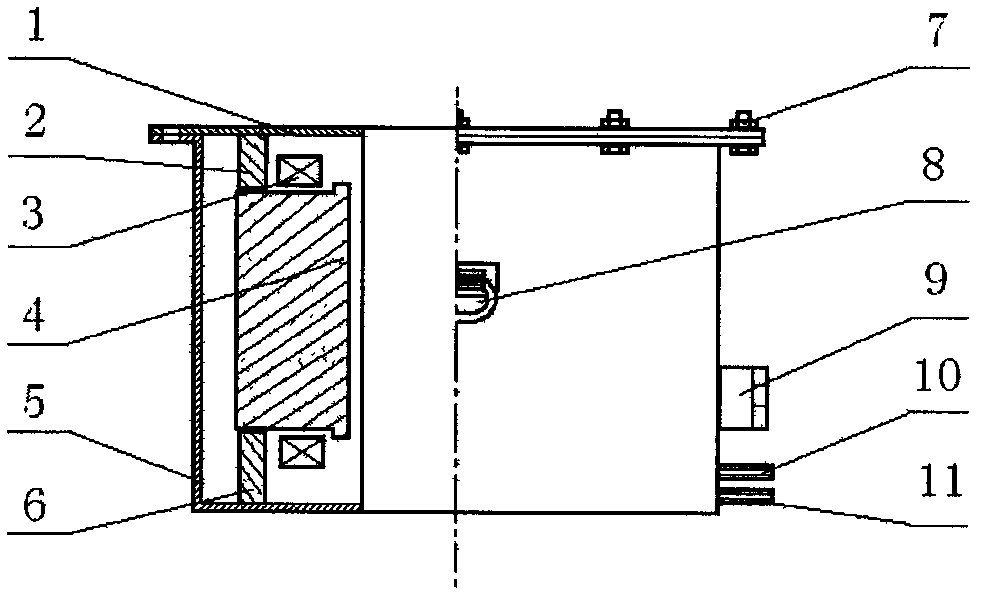
[0025] It consists of a set of coil windings 3 and a magnetic yoke set made of silicon steel. The coil 3 is made of a hollow copper wire, and the inside can be cooled by cooling water. After the coil is insulated, it is placed on the yoke, and the yoke is supported and fixed in the box body 5 by the lower block 6 and the upper block 2 . The magnitude of the current passed through the coil 3 is an important factor affecting the stirring effect, and the current should be adjustable within the range of 0 to the rated current according to needs. The inclined yoke end face 4 is the key of the present invention. Each yoke end face 4 is inclined relative to the yoke back 12, and is inclined 30° relative to the vertical direction. The height of the yoke group is 80mm, and eac...

Embodiment 2

[0033] Embodiment 2: as Figure 5 and 6 As shown, it is suitable for the spiral electromagnetic stirring device where the cast slab is a slab.

[0034] 1. Electromagnetic induction system

[0035] It consists of a set of yokes with high saturation magnetic induction and high permeability and coils 3 wound on the yokes. Such as Figure 5 and Figure 6As shown, the yoke set is composed of a yoke back 12 and several yoke end faces 4, which are arranged in a straight line. The end face 4 of the yoke is inclined relative to the back 12 of the yoke, and the included angle with respect to the vertical direction is 25°. The height of the yoke group is 200 mm, and the gap between the end faces 4 of the yoke is 20 mm. A total of seven yoke end faces 4 are arranged in a straight line, and more yoke end faces 4 may form a linear shape similar to a traveling wave magnetic field stirrer for spiral stirring of slabs and long and narrow areas. The yoke group is fixed in the box body 5 b...


PUM

PropertyMeasurementUnit
heightaaaaaaaaaa

Abstract

The invention discloses a simple and effective helical electromagnetic stirring device capable of fully stirring molten metal. The helical electromagnetic stirring device comprises an electromagnetic induction system, a power supply system, a cooling system and a box body (5), wherein the electromagnetic induction system consists of a magnet yoke group and coils (3) sleeved on the magnet yoke group; the helical electromagnetic stirring device is characterized in that the magnet yoke group consists of a magnet yoke back part (12) and a plurality of magnet yoke end planes (4) connected with the magnet yoke back part; and the magnet yoke end planes (4) are arranged in a tilted manner opposite to the magnet yoke back part (12). According to the helical electromagnetic stirring device, the stirring device can be applied to metal continuous casting, semi-solid state continuous casting and directional solidification processes.

Description

technical field [0001] The invention belongs to the field of electromagnetic casting and material electromagnetic processing and molding, in particular to a helical magnetic field electromagnetic stirring device for metal continuous casting, semi-solid casting and directional solidification process. Background technique [0002] With the rapid development of science and technology, all walks of life have put forward higher requirements on the performance of materials, which has prompted people to continuously develop new materials and new technology research of traditional materials. The electromagnetic field is one of the important physical fields in nature. It has many advantages that cannot be compared with thermoelectric technology. The most notable feature is that it can transfer heat and kinetic energy to the metal melt, and there is no contact between the melt and the magnetic field generator. The metal melt is free from contamination. Electromagnetic stirring is an ...

Claims


Application Information

Patent Timeline
Patent Type & Authority Applications(China)
IPC IPC(8): B22D27/02B22D11/115B22D11/049
Inventor 郭庆涛廖相巍李德刚贾吉祥李广帮
Owner ANGANG STEEL CO LTD
Why Eureka
Try Eureka