
Slab continuous casting machine crystallizer flow field control device

A technology of slab continuous casting machine and control device, which is applied in the field of slab continuous casting electromagnetic metallurgy, can solve the problems of complex flow field and unstable flow field state of the crystallizer, so as to improve the metallurgical effect, improve the quality of the slab, and improve the The effect of axial crystal ratio

Pending Publication Date: 2022-01-21
HUNAN KEMEIDA ELECTRIC
View PDF2 Cites 0 Cited by
  • Summary
  • Abstract
  • Description
  • Claims
  • Application Information

AI Technical Summary

Problems solved by technology

[0003] Chinese patent CN201620699034.9 discloses a multi-functional and multi-mode electromagnetic flow control device for slab continuous casting mold. The role of blank electromagnetic brake
Chinese patent CN201710107017.0 discloses a method for controlling the flow field of a slab continuous casting mold. The upper part of the electromagnetic stirring device and the lower part of the electromagnetic brake, for high-speed conditions, the upper part has no braking function
[0005] The flow field of the mold in slab continuous casting is complex and the state of the flow field is unstable, so a more reasonable flow field control device is required to adapt to the mold of the slab continuous casting machine with a wide casting speed range

Method used


Image

  • Slab continuous casting machine crystallizer flow field control device
  • Slab continuous casting machine crystallizer flow field control device
  • Slab continuous casting machine crystallizer flow field control device

Examples


Embodiment Construction

[0035] The following will clearly and completely describe the technical solutions in the embodiments of the present invention with reference to the accompanying drawings in the embodiments of the present invention. Obviously, the described embodiments are only some, not all, embodiments of the present invention. All other embodiments obtained by persons of ordinary skill in the art based on the embodiments of the present invention belong to the protection scope of the present invention.

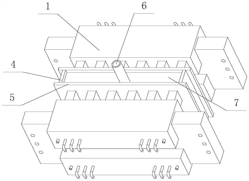
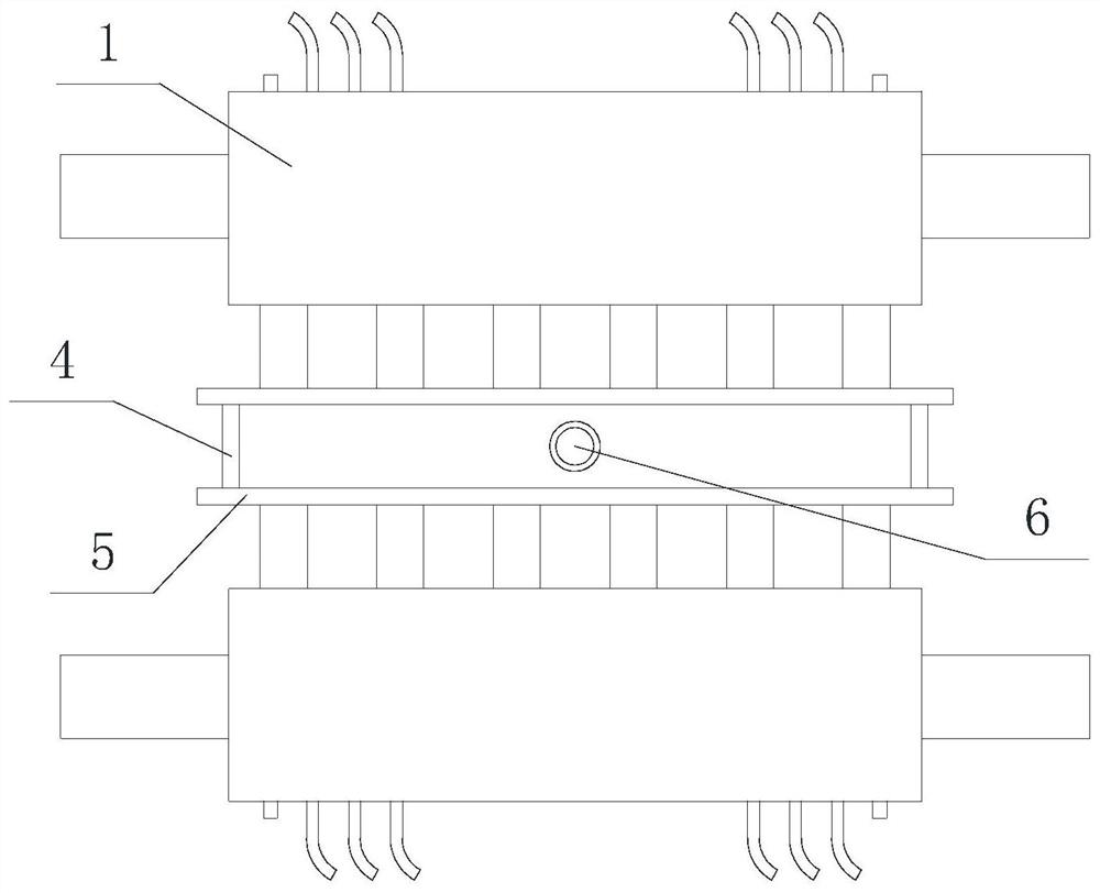
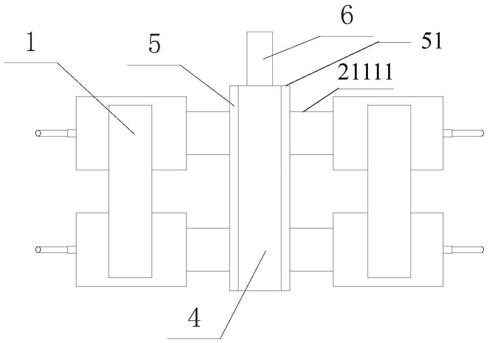
[0036] Such as Figure 1-5 As shown, a mold flow field control device for a slab continuous casting machine includes two flow field control components 1 and a control module, and the two flow field control components 1 are symmetrically distributed on two mold wide copper plates 5 On the side, the flow field control assembly 1 includes two independently controlled magnetic field generators 2 and a non-magnetic connection block 3 connecting the two magnetic field generators 2, the two magnetic...


PUM


Abstract

The invention discloses a slab continuous casting machine crystallizer flow field control device. The slab continuous casting machine crystallizer flow field control device comprises two flow field control assemblies and a control module, the two flow field control assemblies are symmetrically distributed on the two sides of two crystallizer wide-face copper plates, the flow field control assembly comprises two magnetic field generators which are independently controlled and a non-magnetic connecting block which is connected with the two magnetic field generators, the two magnetic field generators are an upper magnetic field generator and a lower magnetic field generator respectively, each magnetic field generator comprises a shell, an inductor for generating an alternating-current magnetic field or a direct-current magnetic field is arranged in the shell, a plurality of cables are connected to the two sides of the end face of the outer side of the shell, the cables are connected with a power source through the control module, and the control module is located in a production line control cabinet. According to the slab continuous casting machine crystallizer flow field control device, an alternating current mode, a braking mode and a mixing mode are arranged, the flow control effect of an electromagnetic field is conducted on molten steel, the effects of reducing fluctuation of a meniscus of a crystallizer, reducing casting blank slag, improving the axial crystal rate of a casting blank and the like are achieved, and therefore the metallurgical effect of the casting blank is improved.

Description

technical field [0001] The invention relates to the technical field of slab continuous casting electromagnetic metallurgy, in particular to a flow field control device for a mold of a slab continuous casting machine. Background technique [0002] The flow field control of the continuous casting machine mold is very important to the quality control of the slab, and the flow rate control of the upper stream and the lower stream of the mold is very important. When the casting speed is low, it is not conducive to the flow of molten steel in the mold, and it is not conducive to the purification of molten steel and the floating of slag inclusions; when the casting speed is high, the impact depth of the downstream is too deep, and it is difficult for air bubbles and slag inclusions to float up . [0003] Chinese patent CN201620699034.9 discloses a multi-functional and multi-mode electromagnetic flow control device for slab continuous casting mold. The role of blank electromagneti...

Claims


Application Information

Patent Timeline
Patent Type & Authority Applications(China)
IPC IPC(8): B22D11/115B22D11/18
CPCB22D11/115B22D11/18
Inventor 张凯陈勇彪任继权申艳聪魏石磊周鑫罗兵
Owner HUNAN KEMEIDA ELECTRIC
Learn More