Eureka AIR delivers breakthrough ideas for toughest innovation challenges, trusted by R&D personnel around the world.

Center-feeding cyclone pulverized coal combustion device adopting pre-combustion chamber and double-layer jet flow to separate secondary air

A pulverized coal combustion and jet separation technology, which is applied in the direction of burners, combustion methods, combustion types, etc., can solve the problems of high emissions, serious slagging, poor flame stability, etc., achieve enhanced graded combustion, and reduce NOx emissions Effect

Inactive Publication Date: 2018-01-09
HARBIN INST OF TECH
View PDF8 Cites 11 Cited by
  • Summary
  • Abstract
  • Description
  • Claims
  • Application Information

AI Technical Summary

Problems solved by technology

[0007] The present invention solves the problem of NO x High emissions, poor flame stability, severe slagging and poor burnout, and then provide a center-feeding swirling pulverized coal combustion device that uses a pre-combustion chamber and double-layer jets to separate the secondary air

Method used


Image

  • Center-feeding cyclone pulverized coal combustion device adopting pre-combustion chamber and double-layer jet flow to separate secondary air
  • Center-feeding cyclone pulverized coal combustion device adopting pre-combustion chamber and double-layer jet flow to separate secondary air
  • Center-feeding cyclone pulverized coal combustion device adopting pre-combustion chamber and double-layer jet flow to separate secondary air

Examples


specific Embodiment approach 1

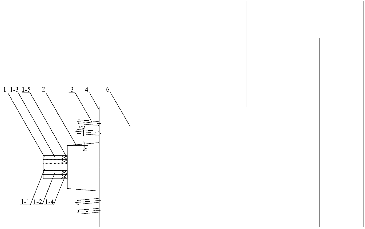
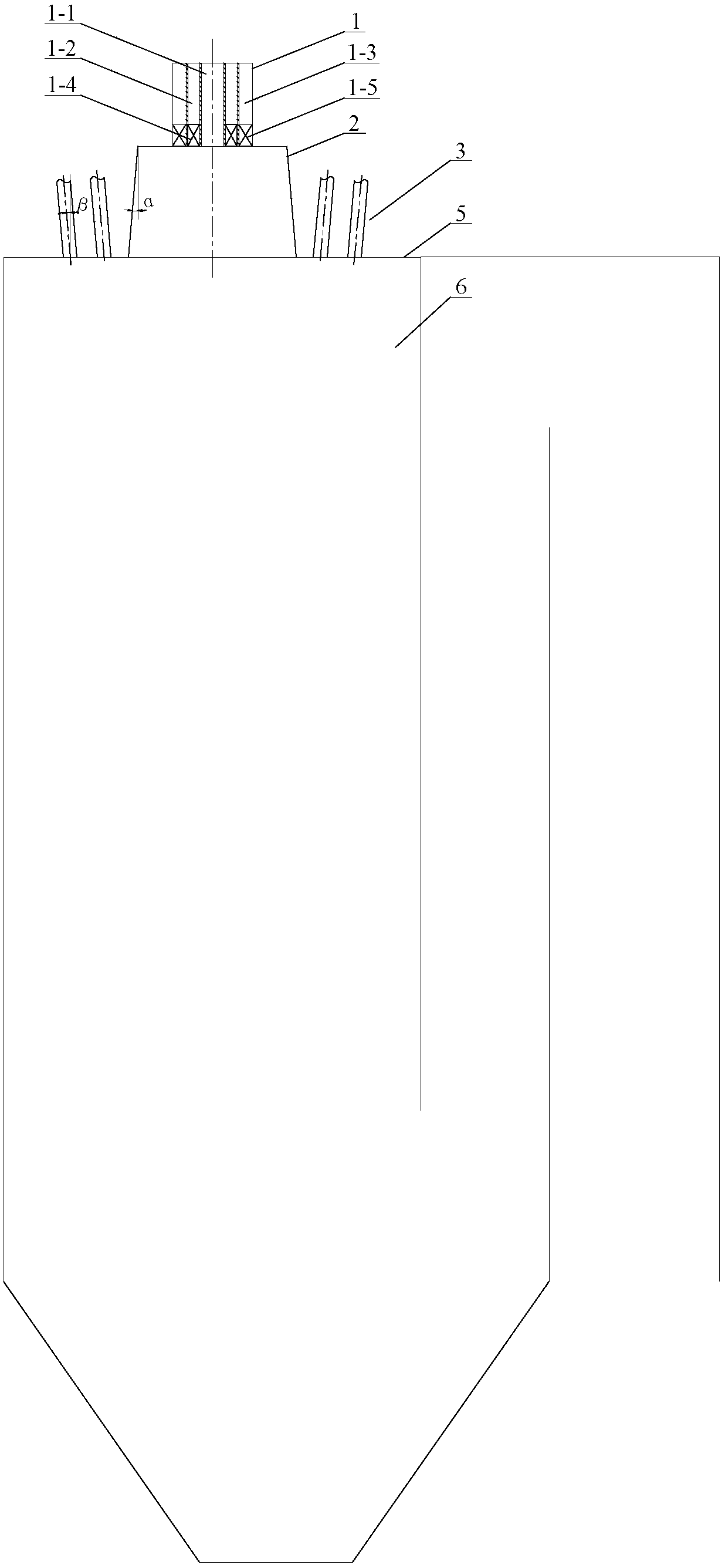
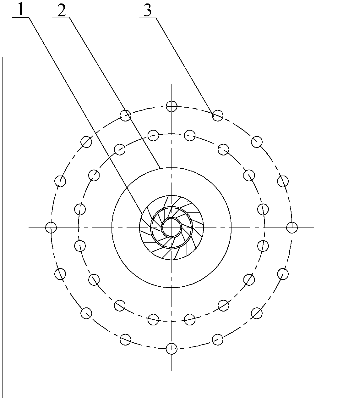
[0033] Specific implementation mode one: as Figure 1~4 As shown, the central powder-fed swirl pulverized coal combustion device using the pre-combustion chamber and double-layer jet flow separation secondary air in this embodiment includes a swirl pulverized coal burner 1, a pre-combustion chamber 2 and a plurality of separated secondary air nozzles 3. The pulverized coal combustion device is installed on the front wall 4 of the boiler or placed on the roof 5 of the vertical boiler; the swirl pulverized coal burner 1 includes a primary air duct 1-1, a secondary air duct in the swirl The air duct 1-2 and the secondary air duct 1-3 outside the swirl flow, the secondary air duct 1-2 inside the swirl flow is arranged outside the primary air duct 1-1, and the secondary air duct 1-3 outside the swirl flow 3. Set outside the secondary air duct 1-2 in the swirl flow, the primary air duct 1-1, the secondary air duct 1-2 in the swirl flow and the secondary air duct 1-3 outside the swir...

specific Embodiment approach 2

[0037] Specific implementation mode two: as figure 1 and figure 2 As shown, the pre-combustion chamber 2 in this embodiment is cast from high-strength refractory materials, and the diameter of the inlet end of the pre-combustion chamber 2 is 1.5 to 3 times the outer diameter of the secondary air pipe 1-3 outside the swirling flow. The length of the chamber 2 is 0.8-2 times of the outer diameter of the secondary air pipe 1-3 outside the swirling flow, and the expansion angle α between the inlet end and the outlet end of the pre-combustion chamber 2 is 0-45°. Such a design can ensure the stable combustion of pulverized coal, and at the same time blow the gas flow of pulverized coal in the pre-combustion chamber out of the pre-combustion chamber in time to avoid slagging in the pre-combustion chamber. Other components and connections are the same as those in the first embodiment.

specific Embodiment approach 3

[0038] Specific implementation mode three: as figure 1 and figure 2 As shown, in this embodiment, the distance between the radial axis between the separated secondary air nozzle 3 and the outlet of the pre-chamber 2 is 0.6-2 times the diameter of the pre-chamber. Such a design can prevent the separated secondary air from mixing with the pulverized coal airflow prematurely, which is beneficial to reduce fuel-type NOx; at the same time, adjusting the radial spacing according to the different coal quality can improve the adaptability to the coal type. . Other compositions and connections are the same as those in Embodiment 1 or 2.


PUM


Abstract

The invention discloses a center-feeding cyclone pulverized coal combustion device adopting a pre-combustion chamber and double-layer jet flow to separate secondary air, and relates to a pulverized coal combustion device, and the center-feeding cyclone pulverized coal combustion device solves the problems that an existing pulverized coal combustion device is high in NOx discharge amount, is poor in flame stability, is severe in slag-bonding and is poor in after-combustion. High-concentration pulverized coal gas flow is conveyed in a primary air tube; a cyclone pulverized coal combustor is arranged at the front end of the pre-combustion chamber; the cyclone pulverized coal combustor and the pre-combustion chamber are coaxially arranged, and each pipeline spray hole of the cyclone pulverizedcoal combustor is flush to the inner wall of the pre-combustion chamber; a plurality of separating secondary air spray holes are distributed at the outer side of the pre-combustion chamber in a double-layer annular mode; a circle on which the centers of each layer of separating secondary air spray holes are located is coaxial with the cyclone combustor; the two layers of separating secondary airspay holes are uniformly crossed with one another; each separating secondary air spray hole is flush to the inner wall of a furnace hearth; and included angles beta between the center lines of the separating secondary air spray holes and the axis of the air tube at each stage of the cyclone combustor are 0-60 degrees. The center-feeding cyclone pulverized coal combustion device is used for an industrial pulverized coal boiler.

Description

technical field [0001] The invention relates to a pulverized coal combustion device for an industrial boiler, in particular to a pulverized coal combustion device with a central powder feeding swirling flow that adopts a pre-combustion chamber and double-layer jets to separate secondary air. Background technique [0002] In my country, coal-fired industrial boilers are the main coal-consuming equipment except power plant boilers, with a total of nearly 600,000 units and an annual coal consumption of nearly 640 million tons. Traditional coal-fired industrial boilers are mainly layer-fired furnaces, that is, fuel is placed on a fixed or moving grate to form a fuel layer, and air is introduced from the bottom of the grate to carry out combustion reactions through the fuel layer. It generally has the problem of low boiler thermal efficiency. Compared with the layer-fired furnace, the industrial pulverized coal boiler adopts the chamber combustion combustion method, and the pulv...

Claims


Application Information

Patent Timeline
Patent Type & Authority Applications(China)
IPC IPC(8): F23D1/02F23L9/00
Inventor 陈智超严蓉刘涛曾令艳李争起
Owner HARBIN INST OF TECH
Why Eureka
Eureka Blog
Learn More