Pulverized coal burner and boiler with same

A pulverized coal burner, pulverized coal technology

Active Publication Date: 2011-04-27
YANTAI LONGYUAN POWER TECH
View PDF5 Cites 11 Cited by
  • Summary
  • Abstract
  • Description
  • Claims
  • Application Information

AI Technical Summary

Problems solved by technology

The technical solution obtains enough fire through the fire interceptor to provide enough heat to ensure continuous combustion of the carbon powder; since the carbon powder is completely burned in the forced ignition internal combustion chamber, the heat of the carbon powder is released in the forced ignition internal combustion chamber , therefore, cannot be applied on the boiler
[0013] The second deficiency is: in the prior art, in order to improve the combustion efficiency of pulverized coal, higher temperature and higher oxygen concentration need to be maintained in the furnace
The timing and amount of supplementary combustion air become the key to the combustion performance of pulverized coal in the boiler. The supplementary combustion air should not be added too late, and the supplementary amount should not be too small, which limits the size of the reducing reaction area and the reduction combustion. degree, which weakens the effect of inhibiting the formation of nitrogen oxides; on the other hand, in order to create a reducing combustion area, the combustion atmosphere of pulverized coal is forcibly destroyed, which will inevitably affect the burnout of pulverized coal and the operation of the boiler. Efficiency has a negative impact
[0018] In short, the scope of the existing low-nitrogen oxide combustion technology is limited to the boiler furnace, and the effect of inhibiting the formation of nitrogen oxides is limited. At the same time, it will reduce the combustion efficiency of the boiler.

Method used


Image

  • Pulverized coal burner and boiler with same
  • Pulverized coal burner and boiler with same
  • Pulverized coal burner and boiler with same

Examples


Embodiment 1

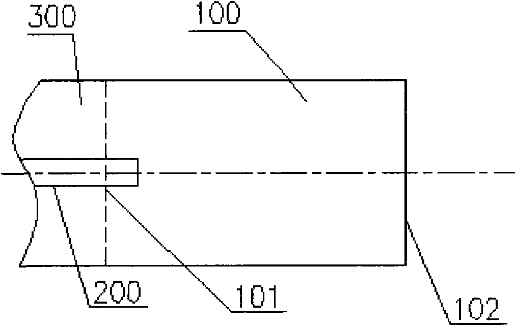
[0055] Please refer to image 3 , which is a schematic structural view of the pulverized coal burner provided in Embodiment 1. The pulverized coal burner includes a fire source 200 and an internal combustion chamber 100, the internal combustion chamber 100 has an inlet 101 and an outlet 102, and a long cylindrical main combustion chamber is formed in it to form a suitable space to maintain the internal pulverized coal flow with a predetermined excess air factor. In this example, the internal combustion chamber 100 also includes a transition duct 300 communicating with the front end of the main combustion chamber, and the fire source 200 extends into the internal combustion chamber 100 from the transition duct 300; the transition duct 300 communicates with the primary air pulverized coal duct.

[0056]In the flow direction of the pulverized coal airflow, the internal combustion chamber 100 has a predetermined length and cross-sectional area, and can maintain the excess air rat...

Embodiment 2

[0066] Please refer to Figure 4 , which is a schematic structural view of the pulverized coal burner provided in Embodiment 2. On the basis of Embodiment 1, the internal combustion chamber 100 includes a main combustion chamber 120 and a deceleration inlet section 110 connected to the front end of the main combustion chamber 120 , and the inlet 101 is located at the intersection of the deceleration inlet section 110 and the transition duct 300 . As shown in the figure, the cross-sectional area of ​​the deceleration inlet section 110 is smaller than the cross-sectional area of ​​the main combustion chamber 120 . When the pulverized coal gas flow enters the main combustion chamber 120 with a large cross-sectional area from the deceleration inlet section 110 with a small cross-sectional area, the flow velocity of the pulverized coal gas flow will decrease accordingly. In this way, when the length of the internal combustion chamber 100 remains unchanged, it takes longer for the ...

Embodiment 3

[0072] When the pulverized coal airflow ignited in the internal combustion chamber 100 is drawn out through the outlet 102 and introduced into the boiler furnace, in order to make the drawn high-temperature pulverized coal combustion flame have higher rigidity and adapt to the overall combustion organization needs of the boiler furnace, it can also be An acceleration outlet section is arranged in the internal combustion chamber 100 . Such as Figure 6 As shown, this figure shows a schematic structural view of the pulverized coal burner provided by Embodiment 3, which also has an accelerated outlet section 130 connected to the rear end of the main combustion chamber 120; similarly, in order to ensure the pulverized coal flow Stability when the flow velocity changes, in the flow direction of the pulverized coal airflow, preferably, the cross-sectional area of ​​the acceleration outlet section 130 gradually decreases, so that the flow velocity of the pulverized coal airflow gradu...


PUM


Abstract

The invention discloses a pulverized coal burner and a boiler with the same. The disclosed pulverized coal burner comprises a heat source and an internal burning chamber, wherein the internal burning chamber ensures that an internal pulverized coal flow has a predetermined excess air coefficient; the heat source is positioned in the internal burning chamber; the internal burning chamber is provided with an inlet, a long cylindrical main burning chamber and an outlet; the heat source can ignite pulverized coal which passes through the internal burning chamber and ensures that the pulverized coal reducibly burns in the internal burning chamber; preferably, the internal burning chamber comprises the main burning chamber and a decelerating inlet section; and the sectional area of the decelerating inlet section is less than that of the main burning chamber. The internal burning chamber of the pulverized coal burner can maintain a smaller air coefficient, so reducing atmosphere is formed in the internal burning chamber; the pulverized coal reducibly burns in the internal burning chamber, so the pulverized coal flow enters a hearth in the form of high-temperature pulverized coal burning flame to improve the burning stability of the pulverized coal; meanwhile, the reducing burning can also convert a nitrogen element into a reducing intermediate product, so that fuel type nitrogen oxides are prevented from being produced.

Description

technical field [0001] The invention relates to a pulverized coal combustion technology, in particular to a pulverized coal burner, and also to a boiler with the pulverized coal burner. Background technique [0002] Currently, the combustion process of the boiler includes two stages: the first stage is the boiler ignition stage, and the second stage is the normal combustion stage. [0003] In the first stage, when the boiler is ignited, in order to ignite the pulverized coal, maintain the combustion of the pulverized coal, and increase the temperature of the furnace, it is often necessary to put in fuel for combustion to ignite the pulverized coal and increase the temperature in the furnace; After the temperature rises to a certain height, it enters the second stage of boiler combustion, that is, the normal combustion stage. [0004] In the normal combustion stage, the input of fuel oil is stopped, and after the pulverized coal enters the furnace, it is ignited under the ac...

Claims


Application Information

Patent Timeline
Patent Type & Authority Applications(China)
IPC IPC(8): F23D1/00F23C5/08
CPCF23C5/08F23D1/00
Inventor 王雨蓬程昌业唐宏张超群张孝勇龚泽儒崔星源
Owner YANTAI LONGYUAN POWER TECH
Why Eureka
Try Eureka