
Water combustion boiler

A boiler and water-burning technology, applied in the field of heating boilers, can solve the problems of large energy consumption, increased heating costs, environmental pollution, etc., and achieve the effects of long service life, simple structure, and easy manufacture

Active Publication Date: 2013-12-18
林亮星
View PDF3 Cites 6 Cited by
  • Summary
  • Abstract
  • Description
  • Claims
  • Application Information

AI Technical Summary

Problems solved by technology

If you want to make the temperature in the boiler reach above 3000℃, you need to consume a lot of energy, which will increase the cost of heating. At the same time, coal, oil, and natural gas are non-renewable resources, and they will release harmful gases during combustion, causing environmental pollution.

Method used


Image

  • Water combustion boiler
  • Water combustion boiler
  • Water combustion boiler

Examples


Embodiment 1

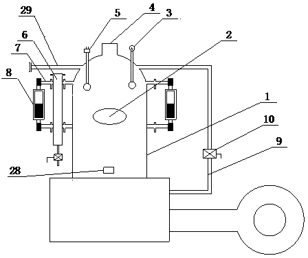
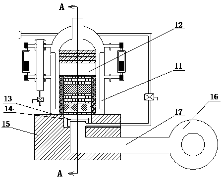
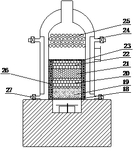
[0046] This embodiment is a water-fired boiler with a structure such as Figure 1-3 As shown, it includes a furnace body 1 with an inner cavity. The shape of the furnace body 1 is n-shaped, a columnar structure with a dome, and is fixed on a furnace base 15 .

[0047]The inner cavity of the furnace body 1 has a diameter of 1700 mm and a height of 3100 mm. The inner cavity of the furnace body 1 is covered with an n-shaped water jacket with the inner wall of the furnace body 1 as the outer wall. The inner wall of the water jacket and the inner wall of the furnace body 1 are n-shaped. The water storage chamber 11, the inner diameter of the columnar part of the water storage chamber 11 is 1400mm, and the outer diameter is 1800mm. The water storage chamber 11 is used to supply water to the boiler and keep the temperature of the combustion chamber 12. The area enclosed by the inner wall of the water jacket is the combustion chamber 12 . The stove base 15 has a section of cylindrica...

Embodiment 2—5

[0068] Embodiment 2-5 is a kind of water-fired boiler respectively, and their difference with embodiment 1 only lies in:

[0069] The weight proportions of rhenium, niobium, magnesium and molybdenum in the combustion-supporting alloy layer 21 are different, see the table below for details.

[0070]

[0071] The structure of embodiment 2-5 is exactly the same as embodiment 1, see for reference figure 1 — image 3 .


PUM

PropertyMeasurementUnit
Heightaaaaaaaaaa
Thicknessaaaaaaaaaa

Abstract

The invention discloses a water combustion boiler which comprises a boiler with an inner cavity. A boiler door is formed in the wall of the boiler, a water jacket is nested in the inner cavity of the boiler, the inner wall of the boiler is used as the outer wall of the water jacket, and a water storage cavity is formed between the inner wall of the water jacket and the inner wall of the boiler; a combustion chamber is formed by the inner wall of the water jacket in an enclosed manner; a ventilation system, water inlet pipes, a steam exhaust pipe, a smoke vent and a steam supply pipe are respectively fixedly arranged on the outside of the boiler, the ventilation system is communicated with the combustion chamber, the water inlet pipes are communicated with the water storage cavity, the steam exhaust pipe and the smoke vent are communicated with the inner cavity of the boiler, and the steam supply pipe is simultaneously communicated with the combustion chamber and the top of the inner cavity of the boiler; an ignition system and a combustion-supporting carrier are fixed into the combustion chamber. The water combustion boiler has the advantages that large quantities of electrons can be released by metal atoms of the combustion-supporting carrier at high temperatures, heat can be released, and hydrogen decomposed from steam can be assisted to be combusted, so that a large quantity of heat can be released; the water combustion boiler is suitable to be used as heating equipment and applicable to modification projects of coal combustion boilers, gas combustion boilers and oil combustion boilers in the fields of power plants and heating, the industrial and agricultural fields and the like, the steam and other fuel can be combusted jointly to generate the heat, so that fifty percents of fuel can be saved on the premise that the same quantity of heat is provided.

Description

technical field [0001] The invention belongs to the field of heating boilers and is used for supplying heat energy. Specifically, it is a water-fired boiler with a combustion-supporting carrier inside and water as fuel. Background technique [0002] Hydrogen has the characteristics of high combustion value, and the product of its combustion is water, which belongs to clean energy. It has always been a dream of people to decompose water into hydrogen and oxygen, let hydrogen burn, let oxygen support the combustion, and directly use water as fuel to achieve combustion. [0003] As a kind of energy conversion equipment, the boiler exchanges the heat energy generated by the combustion of fuel with the heating medium, so as to output steam, water or other medium with high heat. The hot water or steam output by the boiler can directly provide the required heat energy for industrial production and people's life, and can also be converted into mechanical energy through a steam pow...

Claims


Application Information

Patent Timeline
IPC IPC(8): F24H1/26F24H9/18F24H9/20F22B1/00F23L7/00F23B90/06F23B90/08
Inventor 林亮星
Owner 林亮星
Learn More