
Electromagnetic device for stirring metal melt spirally

A technology of spiral electromagnetic stirring and metal melt, which is applied in the fields of electromagnetic casting and electromagnetic processing of materials, can solve the problems of limited spiral stirring effect and unfavorable spiral stirring, and achieves reduction of thermal cracking and macrosegregation, reduction of component segregation, elimination of The effect of shrinkage

Inactive Publication Date: 2014-01-29
UNIV OF SCI & TECH LIAONING
View PDF7 Cites 0 Cited by
  • Summary
  • Abstract
  • Description
  • Claims
  • Application Information

AI Technical Summary

Problems solved by technology

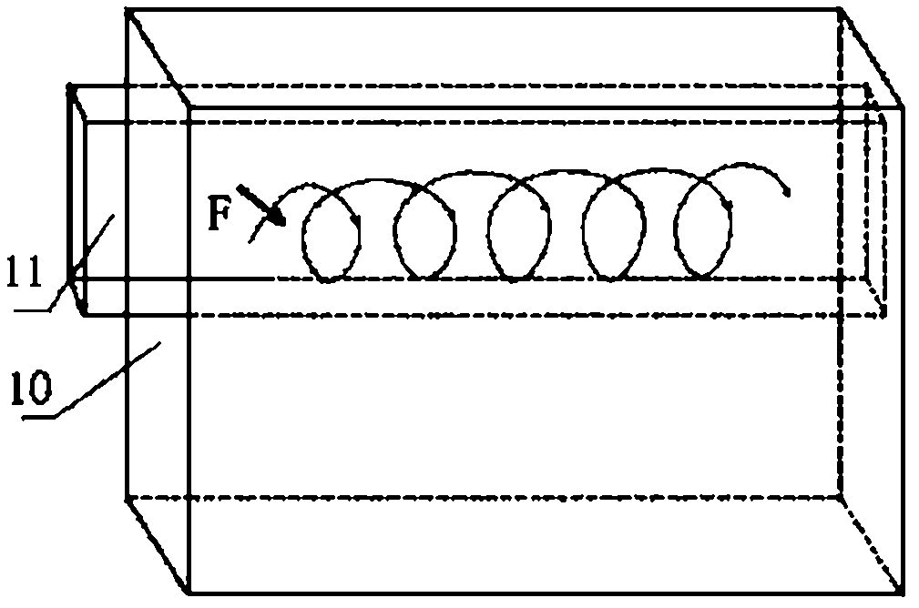
Stacking multiple rotating magnetic field generators up and down together, according to the principle of electromagnetic fluid mechanics, will generate vertical traveling wave force in the metal melt, but it is affected by the number of yoke arrangements on the vertical section and the continuity of the yoke back , the magnitude of this force will be much smaller than the circumferential rotational force, so the spiral stirring effect will be limited
Similarly, with the helical agitation formed by the traveling wave magnetic field juxtaposed in the circumferential direction, the rotational force in the circumferential direction will be much lower than the traveling wave force in the circumferential direction, which is not conducive to effective helical agitation

Method used


Image

  • Electromagnetic device for stirring metal melt spirally
  • Electromagnetic device for stirring metal melt spirally
  • Electromagnetic device for stirring metal melt spirally

Examples


Embodiment Construction

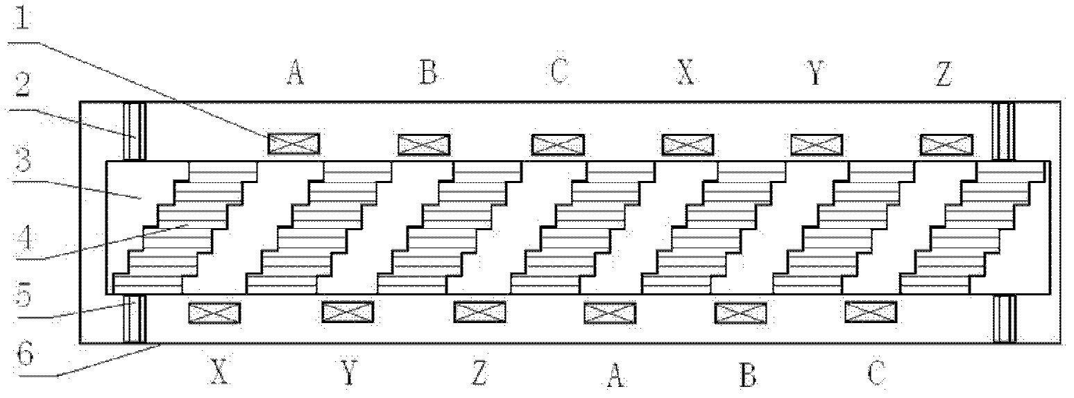
[0025] Such as figure 1 , figure 2 , Figure 6As shown, the electromagnetic induction system is composed of a yoke set and a coil 1 set on the yoke set. The yoke set is composed of a yoke back 3 and 1 to 8 sets of yoke ends 4 connected to the yoke back. The yoke The side of the end portion 4 presents a stepped structure, capable of generating electromagnetic forces in vertical and horizontal directions. The height of the yoke in the electromagnetic induction system is 10~5000mm. The gap between the ends of the yoke is 2~200mm. The transition between the yoke and the end of the yoke is in a circular arc, which is conducive to magnetic conduction. The yoke group is fixed in the box 6 by means of an upper block 2 and a lower block 5 made of insulating material. The coil is wound with copper wire or hollow copper tube. The coil 1 is wound in the gap between the yokes in the Gramm winding, overlapping winding and concentrated winding arrangements. The coil of the electroma...


PUM

PropertyMeasurementUnit
heightaaaaaaaaaa

Abstract

The invention discloses an electromagnetic device for stirring metal melt spirally to improve the effect of stirring the metal melt of a cast billet. The electromagnetic device comprises an electromagnetic sensing system, a power supplying system, a cooling system and a box; the electromagnetic sensing system comprises a magnetic yoke group and a coil winded on the magnetic yoke group; the power supplying system comprise a two or three-phase power supply cabinet and a variable-frequency control cabinet; the cooling system comprises a water inlet and a water outlet on the box and is connected with a water pump and a reservoir through water pipes to form a cooling loop; the box is made of metal or non-metal material; and the electromagnetic sensing system is arranged in the box after being made to be insulating. The electromagnetic device has a simple structure and a wide application range, promotes the formation and the grain refinement of an isometric crystal and the floating of impurities and hereby reduces the defects of thermal cracking and macro-segregating of the cast billet (ingot) and improves the internal and external quality of the continuously cast billet and (ingot).

Description

technical field [0001] The invention relates to the field of electromagnetic casting and material electromagnetic processing and molding, in particular to a metal melt spiral magnetic field electromagnetic stirring device for metal continuous casting, semi-solid casting and directional solidification process. Background technique [0002] The electromagnetic field is one of the important physical fields in nature. It has many advantages that cannot be compared with thermoelectric technology. The most notable feature is that it can transfer heat and kinetic energy to the metal melt, and there is no contact between the melt and the magnetic field generator. The metal melt is free from contamination. Continuous slab casting is a crucial prerequisite in the production process of high-quality slabs. At present, the electromagnetic induction technologies used in the mold of slab continuous casting mainly include: 1. Rotating magnetic field stirring technology, 2. Electromagnetic a...

Claims


Application Information

Patent Timeline
Patent Type & Authority Patents(China)
IPC IPC(8): B22D11/115B22D27/02B22D11/049
Inventor 沙明红李久慧李娜侯忠霖李激光李胜利
Owner UNIV OF SCI & TECH LIAONING
Learn More