Novel vertical numerical-control engraving machine

A CNC engraving machine and vertical technology, applied in the field of engraving machines, can solve the problems of inconvenient disassembly and assembly, large amount of feed, low work efficiency, etc., and achieve the effects of reducing labor intensity, reducing processing errors, and improving work efficiency.

Inactive Publication Date: 2012-12-19
黄泉福
View PDF8 Cites 10 Cited by
  • Summary
  • Abstract
  • Description
  • Claims
  • Application Information

AI Technical Summary

Problems solved by technology

[0003] However, this kind of vertical engraving machine has only one tool, and the engraving process of stone carving, wood carving, metal carving and other materials carving is generally divided into two steps, one is the rough machining of the workpiece, generally using milling, sawing, Rough machining is carried out by means of drilling and other methods, and a certain margin is left for the finishing process during processing; the second is finishing; that is, after the rough machining of the workpiece on the vertical engraving machine, the worker needs to transfer the workpiece to another machine. The engraving machine for fine machining makes the labor intensity of workers high and the work efficiency is low; at the same time, after the workpiece is transferred to the engraving machine for finishing machining, it is necessary to recalibrate the workpiece after rough machining. It is difficult to adjust the fixed position of the axis to be consistent with the fixed position of the axis during rough machining, so that errors will occur in the finishing of the workpiece
Later, some people solved the problems caused by changing the engraving machine by changing the cutting tool. However, due to the large amount of feed in rough machining, milling cutters or drills with larger diameters are generally used, which makes disassembly and assembly more inconvenient.

Method used


Image

  • Novel vertical numerical-control engraving machine
  • Novel vertical numerical-control engraving machine
  • Novel vertical numerical-control engraving machine

Examples


Embodiment Construction

[0024] In order to further explain the technical solution of the present invention, the present invention will be described in detail below through specific examples.

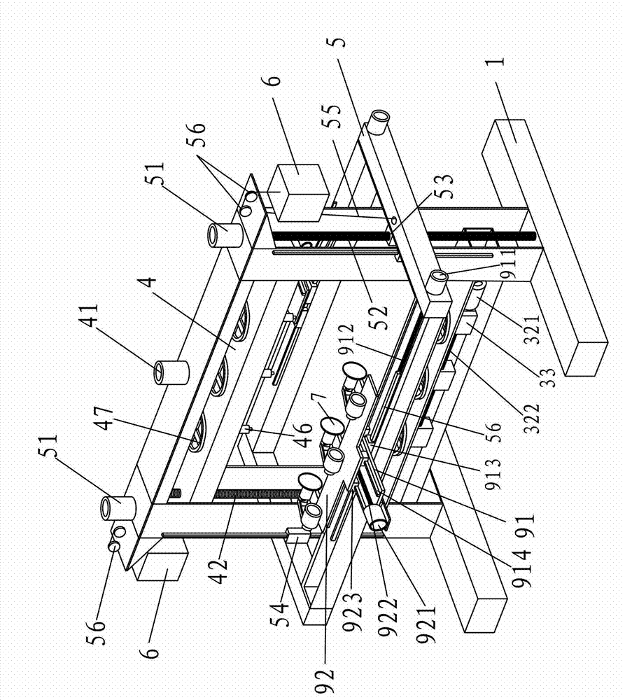
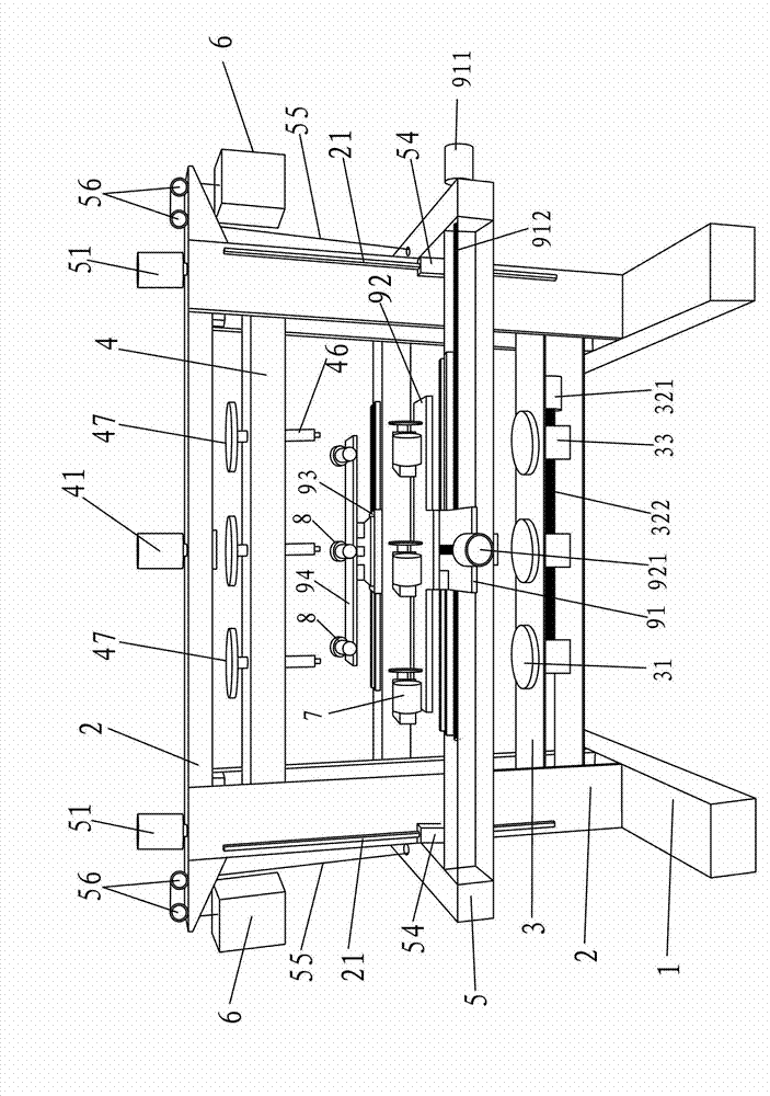
[0025] A kind of novel vertical numerical control engraving machine of the present invention, as figure 1 , 2 As shown, it includes a base 1, a gantry frame 2, a workpiece clamping bottom frame 3, a workpiece clamping top frame 4, and a processing tool rest 5, and the gantry frame 2 is fixed on the base 1.

[0026] The workpiece clamping chassis 3 is a square frame, which is horizontally placed in the bottom of the gantry 2 and fixedly connected with the gantry 2. The upper surface of the workpiece clamping chassis 3 is stacked with Placement tray 31 for placing workpieces to be engraved. The placement tray 31 is a disc. There are at least three placement trays 31. The square frame is provided with a rotation control mechanism that drives the rotation of the placement tray 31. The rotation control mechanism incl...


PUM


Abstract

The invention discloses a novel vertical numerical-control engraving machine which comprises a base, a gantry, a bottom workpiece clamping frame, a top workpiece clamping frame and a machining tool rest. The gantry is fixed on the base, the bottom workpiece clamping frame is arranged in the gantry, the top workpiece clamping frame is arranged above the bottom workpiece clamping frame and is mounted in the gantry in a vertically movable manner, the machining tool rest is mounted on the gantry in a vertically movable manner, a first tool rest and a second tool rest which are capable of moving in all directions are respectively mounted on two sides of the machining tool rest, a first tool used for rough machining is mounted on the first tool rest, and a second tool used for finish machining is mounted on the second tool rest. The novel vertical numerical-control engraving machine has the advantages that without changing the engraving machine or detaching or changing the tools, workpieces to be engraved can be subjected to finish machining after rough machining, so that labor intensity of workers is reduced greatly, engraving precision is increased, machining errors are reduced, and work efficiency is improved.

Description

technical field [0001] The invention relates to an engraving machine. Background technique [0002] Existing vertical CNC engraving machine, such as the vertical CNC engraving machine disclosed by the publication number CN202186217U utility model patent disclosed on April 11, 2012, it includes a base and a gantry frame fixed on the top of the base, on the front end of the base The side is provided with a multi-axis headstock with the spindle head facing upwards and a vertical slide rail, and a multi-axis tailstock matched with the multi-axis headstock is arranged on the vertical slide rail, and the multi-axis headstock and the multi-axis tailstock Coaxial setting, in order to clamp the workpiece, the gantry is equipped with a lifting beam, the lifting beam is equipped with a tool holder that can move left and right and forward and backward, and the tool holder is equipped with a tool corresponding to the multi-axis spindle box. knives. This kind of vertical engraving machi...

Claims


Application Information

Patent Timeline
Patent Type & Authority Applications(China)
IPC IPC(8): B44B1/00B44B1/06B44B3/00B44B3/06
Inventor 黄泉福
Owner 黄泉福
Why Eureka
Try Eureka