Booster bicycle provided with rotary table type sensor provided with magnetic blocks with adjustable positions and magnetic fluxes

A technology for assisting bicycles and sensors, which is applied in the direction of transmission of sensing components, vehicle components, transportation and packaging using electric/magnetic devices, and can solve problems such as different, no control signals, and inconsistencies.

Active Publication Date: 2012-12-19
南通华德锻压机床有限公司
View PDF8 Cites 0 Cited by
  • Summary
  • Abstract
  • Description
  • Claims
  • Application Information

AI Technical Summary

Problems solved by technology

[0016] Disadvantages (1) Using two permanent magnets with no difference to represent the fixed positions of the two pedals, only multiple Halls can be used to represent the rotational positions of the pedals: the two permanent magnets have no difference, and the advantages It is possible to indicate the fixed position of the two pedals regardless of the left and right feet, so that the left and right feet can generate power assistance requirements, which can produce the same motor power assistance effect; but the disadvantage is that the permanent magnet itself cannot indicate the rotation position of the pedals, but only Multiple Halls can be set at different corner positions to indicate the rotational position of the pedal, so one Hall cannot be used, but multiple Halls must be used
[0017] Disadvantage (2) You can’t use only one Hall, but three Halls will inevitably cause the original segmentation error of the three control signals, which will distort the power-assisted demand model, and naturally produce power-assisted output inconsistent with the power-assisted demand: whether the power-assisted bicycle is one or two For a motor, the sensing signal for controlling the motor can only be achieved by inputting a sensing signal into the motor controller to achieve the purpose of controlling the motor; while the patent uses three Halls to control the motor, it is necessary to use the three Halls of the three Halls to control the motor. The signals are combined into one combined control signal before being input to the motor controller
The sensing parameters of the three Halls cannot be the same, especially due to changes in ambient temperature and long-term use, the sensing parameters of the three Halls may vary greatly. The output voltages are different, resulting in different power output of the motor, and the power output is inconsistent with the power demand; similarly, when the power demand is the same, the outputs of different Halls may be the same voltage, resulting in the same power output of the motor, and also There is a problem that the power output is inconsistent with the power demand
[0018] Disadvantage (3) The combined control signal is prone to signal drift, which makes the combined control signal not match the motor controller, and the power-assisted demand model is distorted: due to changes in ambient temperature and long-term use, the sensing parameters of the three Halls may vary greatly , the connection points of the three control signals of the three Halls must change, then the combined control signals generated by the same boost demand will produce segmental signal drift, and the combined control signals will produce signal distortion as a whole, that is, the power boost demand model distortion , causing the motor controller to choose any one of the three control signals as a reference will cause the problem that the power output is inconsistent with the power demand
[0019] Disadvantage (4) The sensing points cannot be increased arbitrarily. If there are too few sensing points, the motor will not run smoothly, making the rider feel very uncomfortable: due to the disadvantages (1) and (2) are the most important The number of halls is greater than one. Obviously, the more the number of halls, the more serious the shortcomings (1) and (2) are.
Therefore, the power-assisted bicycle provided by this patent can only be a very bad power-assisted bicycle that makes the rider feel comfortable.
[0020] Disadvantage (5) The blind area of ​​the signal is up to 42 degrees, and you can't get it when you need it when you start it: As we all know, the torque of the bicycle pedal is the smallest at the apex, and the 10-45 degrees away from the apex is the area that needs the most assistance. , but the included angle between the Halls in this patent is 42.5-43.5 degrees. There is no Hall in the area where the pedal is 10-42 degrees away from the apex, and there is no control signal. The result is when the power is most needed , but the motor of the power-assisted bicycle does not assist
[0021] In short, this patent is a technical solution for using multiple Halls to control the booster mode, because only multiple Halls can be used to represent the rotation position of the pedal, and the multiple control signals of multiple Halls must have original errors, and the combined control signals It is also easy to produce signal drift, which can cause distortion of the assist demand model, that is, the same assist demand at different times, but different assist effects; the more the number of Halls, the more serious the distortion of the assist demand model, limiting the number of Halls , a small amount of Hall will cause the motor to run unsteadily, making the rider feel very uncomfortable, and will not get assistance when starting
To make it undistorted to help the demand model, and to ensure the smooth operation of the motor, there are always two issues. It is impossible to have both.

Method used


Image

  • Booster bicycle provided with rotary table type sensor provided with magnetic blocks with adjustable positions and magnetic fluxes
  • Booster bicycle provided with rotary table type sensor provided with magnetic blocks with adjustable positions and magnetic fluxes
  • Booster bicycle provided with rotary table type sensor provided with magnetic blocks with adjustable positions and magnetic fluxes

Examples


Embodiment 1

[0135] Embodiment 1. A power-assisted bicycle equipped with multi-magnet position and magnetic flux adjustable turntable sensors

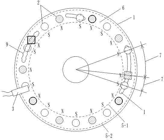
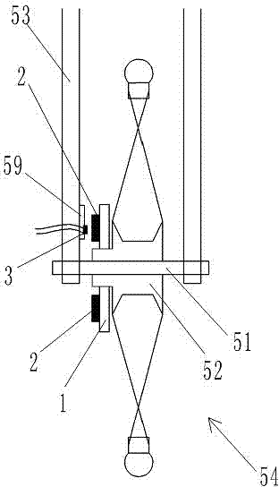
[0136] Such as figure 1 , 3 , 4, 6,

[0137] 1. The components and structure of the electric bicycle related to the installation of the sensor: the two ends of the central axis 51 of the wheel of the electric bicycle are fixedly connected with the frame 53 of the electric bicycle, and the central axis 51 is covered with a hub 52 with a sleeve, and the hub 52 with a sleeve is on the central axis 51 external rotation, the hub 52 with a cover is fixedly connected with the wheel 54 of the bicycle, and the hub 52 with a cover rotates synchronously with the wheel 54; the battery 55 of the electric bicycle is connected to the motor controller 29, and the motor controller 29 is connected to the motor 30 on the wheel;

[0138] 2. The structure of the sensor and the connection relationship of the components are as follows:

[0139] [1] The sensing elemen...

Embodiment 2

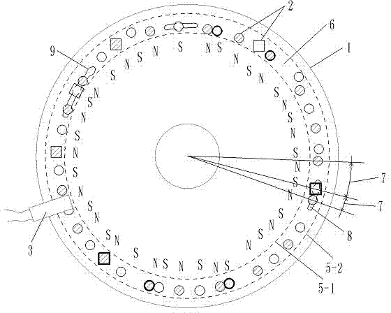
[0160] Embodiment 2, a power-assisted bicycle with adjustable turntable sensors in high-density multi-magnet position and magnetic flux

[0161] Such as figure 2 , 3 , 4, 6, one surface of a high-strength aluminum rotating disk 1 with a diameter of 10.0 cm is provided with 40 permanent magnet blocks 2 with a diameter of 0.6 cm. The magnetic flux of the permanent magnet block 2 is 146---279 (B·H)max / KJ·m -3 Different selection values ​​within the range, and the magnetic flux of the adjacent permanent magnet block 2 is not equal, Hall 3 keeps a distance of 0.2 cm from each permanent magnet block 2 in the rotating state, so that each permanent magnet block 2 that is rotating Hall 3, Hall 3 can generate a corresponding rectangular wave signal output. Other structures are the same as in Embodiment 1.

Embodiment 3

[0162] Embodiment 3, a power-assisted bicycle equipped with a turntable sensor with multiple magnetic block positions and magnetic fluxes with a specific circuit

[0163] Such as figure 1 , 3 , 5, 6, as in embodiment 1, the sensor includes a sensing element connected in sequence, a booster model processor 21, a digital-to-analog converter 27 and an operational amplifier 28;

[0164] [1] The Hall 3 in the sensing element is UGN3075; the structure of other elements and elements in the sensing element is the same as that in Embodiment 1;

[0165] [2] The auxiliary model processor 21 selects the single-chip microcomputer 31 to complete all functions, and the single-chip microcomputer 31 selects AT89S52. That is, the AT89S52 single-chip microcomputer 31 completes all functions of the analog-to-digital conversion and the wave width peak recognizer 22 , the power-assisted starting point selector 23 , the magnet speed calculator 24 , the power-assisted model memory 25 and the power...


PUM


Abstract

The invention relates to a booster bicycle provided with a rotary table type sensor provided with a plurality of magnetic blocks with adjustable positions and magnetic fluxes, and in particular relates to an electric booster bicycle used for providing booster signals for a plurality of point positions in a way of magnetic induction. The sensor comprises a sensing element, a booster model processor, a digital/ analog (D/ A) converter and an operational amplifier which are sequentially connected, wherein a rotary table of the sensing element is fixedly provided with the plurality of permanent magnet blocks, and every two adjacent permanent magnet blocks have the opposite magnetic polarities; the gaps among the permanent magnet blocks can be adjusted, and the positions of the magnet blocks with different magnetic fluxes can be adjusted; the rotary table is arranged on the central shaft of each wheel of the bicycle; a Hall of the sensing element is arranged on a frame close to the permanent magnet blocks; and the operational amplifier is connected with a motor controller. The booster bicycle has the advantages that square-wave signals can be obtained by the Hall, the sensor can conveniently use an artificial set booster model through digital processing output, the booster model is adjusted to be reasonable in boosting starting point, finishing point and force, human can cooperate with a machine in a best way, and the electricity is saved.

Description

technical field [0001] The invention belongs to the technical field of power-assisted bicycles, in particular to an electric power-assisted bicycle that performs multi-point magnetic induction on a rotating part to provide power-assisted signals. Background technique [0002] The Chinese patent 201020295192.0 "Claw Type Torque Sensing Device" applied by Yebao Vehicle Material Industry (Kunshan) Co., Ltd. discloses a sensing device for power-assisted bicycles. The sensing device includes a magnetic part and an elastic part to sense the torque. sensing device. After a long time of use, the change of the elastic coefficient of the elastic member will lead to changes in the sensing signal and the control effect of the controlled motor, and the power-assisted effect will not match the power-assisted needs of people. Moreover, the design structure of the elastic member is complex and the manufacturing cost is high. [0003] The Chinese patent 01201843.0 "Automatic Detection Devi...

Claims


Application Information

Patent Timeline
Patent Type & Authority Applications(China)
IPC IPC(8): B62M6/50G01D5/244
Inventor 黄强
Owner 南通华德锻压机床有限公司
Why Eureka
Try Eureka