Fuel injection device
A fuel injection device and a technology of fuel injection, which can be applied to fuel injection devices, special fuel injection devices, fuel injection valves driven by fluid pressure, etc., and can solve problems such as deterioration of control performance
- Summary
- Abstract
- Description
- Claims
- Application Information
AI Technical Summary
Problems solved by technology
Method used
Image
Examples
no. 1 example
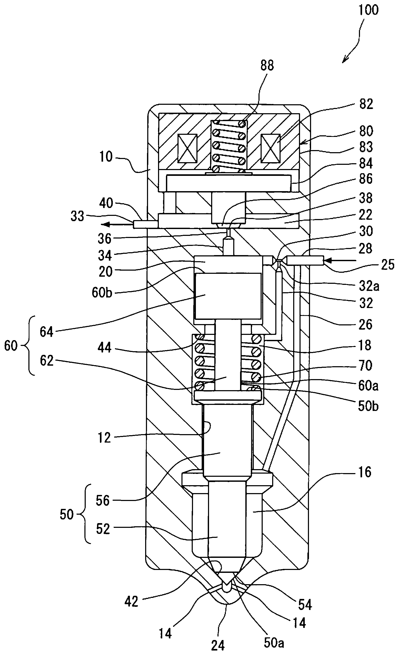
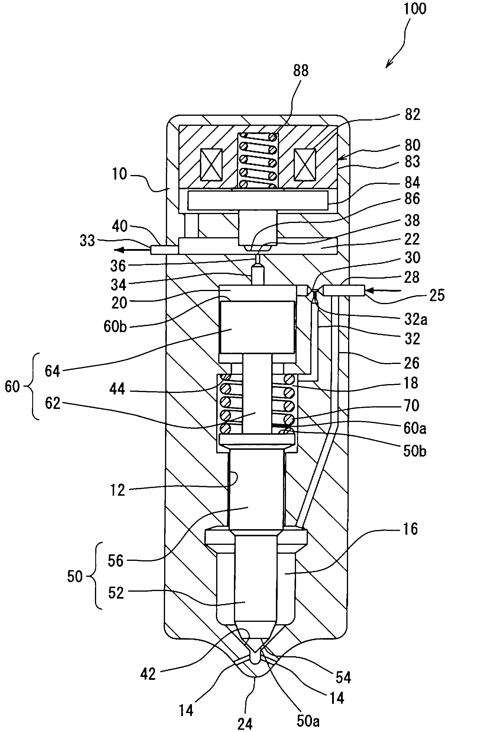
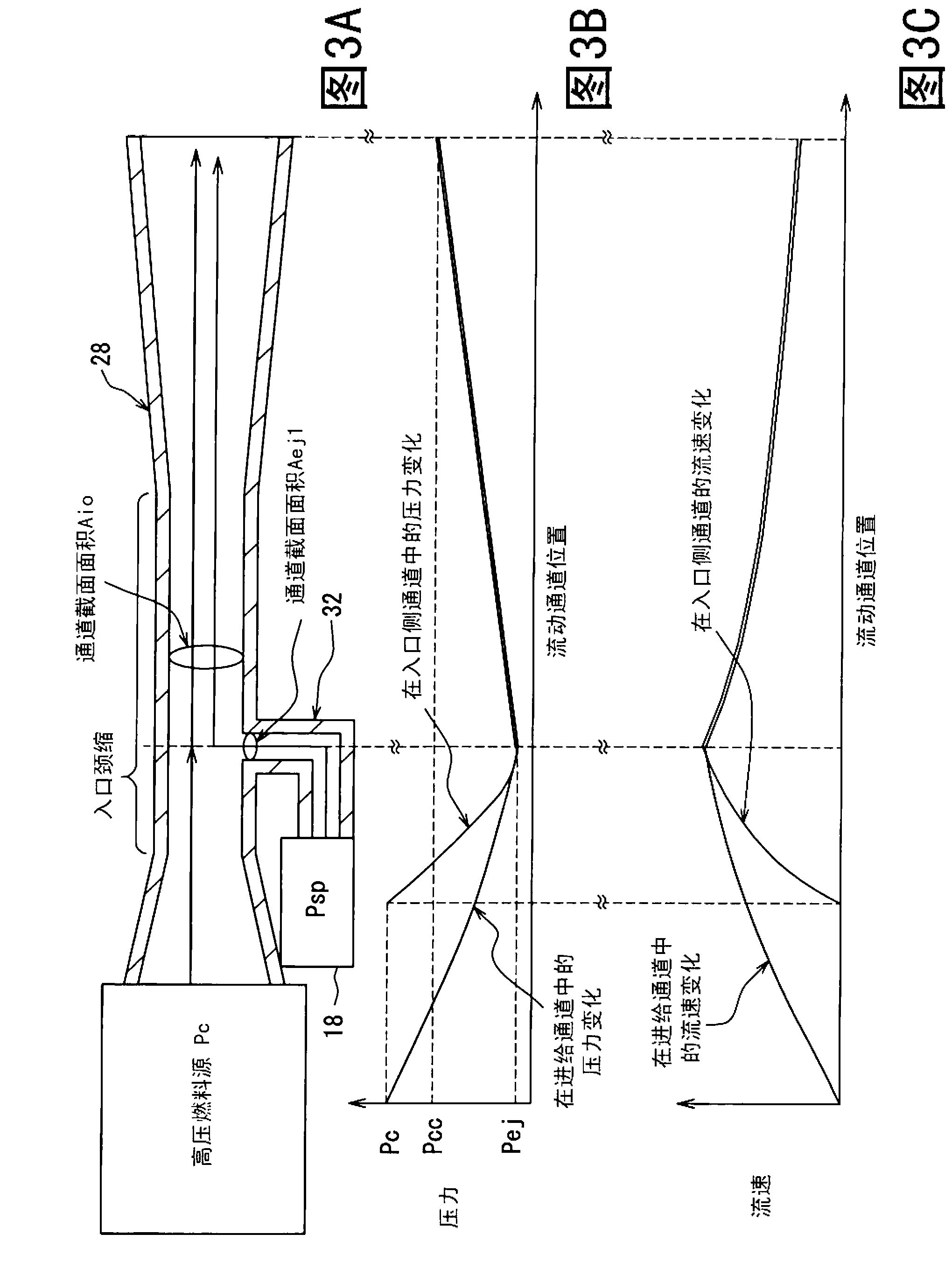
[0030] refer to figure 1 to 4 and Figure 12 A description is given of the first embodiment of the present invention. figure 1 is a cross-sectional view showing the fuel injection device 100 of the first embodiment in which its fuel injection hole 14 is closed.
[0031] The fuel injection device 100 injects fuel into a combustion chamber (not shown) of an internal combustion engine that uses liquid gas type dimethyl ether (DME) as fuel. The fuel injection device 100 is installed for each cylinder, which forms a combustion chamber of the internal combustion engine. The fuel injection device 100 controls fuel injection according to an injection command signal received from an electronic control device (not shown).
[0032] Next, dimethyl ether will be explained. DME is synthesized using natural gas, coal bed methane, coal, or biomass as a raw material, and includes ether linkages in which carbon is held together by oxygen. DME has a higher cetane number than light oil and, ...
no. 2 example
[0092] Figure 6 is a cross-sectional view of a fuel injection device 200 according to a second embodiment of the present invention, showing the closed state of the injection hole 14 . This embodiment is similar to the first embodiment except that the discharge side passage 46 is formed in the fuel injection device 200 instead of the inlet side passage 32 of the fuel injection device 100 of the first embodiment. The discharge side passage 46 is a passage connecting the discharge passage 34 and the spring chamber 18 . An end portion of the discharge-side passage 46 on the side of the discharge-side passage 34 opens in the outlet constriction 36 . The discharge side channel 46 has a discharge side constriction 46 a at the portion of the discharge side channel 46 that opens into the inner wall of the outlet constriction 36 . The passage cross-sectional area (minimum passage cross-sectional area) Aej2 of the discharge-side constriction 46 a is smaller than the passage cross-sect...
no. 3 example
[0112] Figure 9 is a cross-sectional view of a fuel injection device 300 according to a third embodiment of the present invention, showing the closed state of the injection hole 14 . In this embodiment, the discharge side passage 46 of the fuel injection device 200 of the second embodiment is added to the fuel injection device 100 of the first embodiment, and a check valve 48 is provided in the middle of the inlet side passage 32 . One-way valve 48 enables fuel to flow from spring chamber 18 to feed passage 28 but does not allow fuel to flow from feed passage 28 to spring chamber 18 .
[0113] Even with this configuration, when the discharge passage 34 is opened with the valve element 86 , the fuel of the spring chamber 18 is output from the spring chamber 18 through the inlet-side passage 32 and the discharge-side passage 46 . Therefore, the spring chamber pressure Psp may be reduced during the valve opening time of the nozzle needle 50 and the valve closing time of the noz...
PUM
 Abstract
Description
Claims
Application Information
 - R&D
- Intellectual Property
- Life Sciences
- Materials
- Tech Scout
- Unparalleled Data Quality
- Higher Quality Content
- 60% Fewer Hallucinations
Browse by: Latest US Patents, China's latest patents, Technical Efficacy Thesaurus, Application Domain, Technology Topic, Popular Technical Reports.
© 2025 PatSnap. All rights reserved.Legal|Privacy policy|Modern Slavery Act Transparency Statement|Sitemap|About US| Contact US: help@patsnap.com


