
Novel magnetic drive oblique gear pair with oblique air-gap magnetic field

A technology of air-gap magnetic field and magnetic transmission, applied in transmission, belt/chain/gear, mechanical equipment, etc., can solve the problem of small torque of permanent magnet gear transmission, and achieve high reliability, long life and no mechanical wear. Effect

Inactive Publication Date: 2012-12-19
余虹锦
View PDF0 Cites 14 Cited by
  • Summary
  • Abstract
  • Description
  • Claims
  • Application Information

AI Technical Summary

Problems solved by technology

The application of rare earth permanent magnet materials in the field of mechanical transmission is only in its infancy at home and abroad. In 2004, British engineers completed the design of a new type of radial magnetic gear from the theory and the specific practice of the prototype, which overcomes the previous permanent magnet gear. The disadvantage of small transmission torque has opened up an important research direction and future application field for the application of permanent magnet materials in the field of mechanical transmission; at present, the structure of transverse magnetic field magnetic gear with large transmission torque and the comprehensive transverse magnetic field and radial There are no research results on the oblique air gap magnetic field magnetic gear structure with magnetic field characteristics

Method used


Image

  • Novel magnetic drive oblique gear pair with oblique air-gap magnetic field
  • Novel magnetic drive oblique gear pair with oblique air-gap magnetic field
  • Novel magnetic drive oblique gear pair with oblique air-gap magnetic field

Examples


Embodiment Construction

[0025] Below in conjunction with accompanying drawing and specific embodiment, the present invention will be further described:

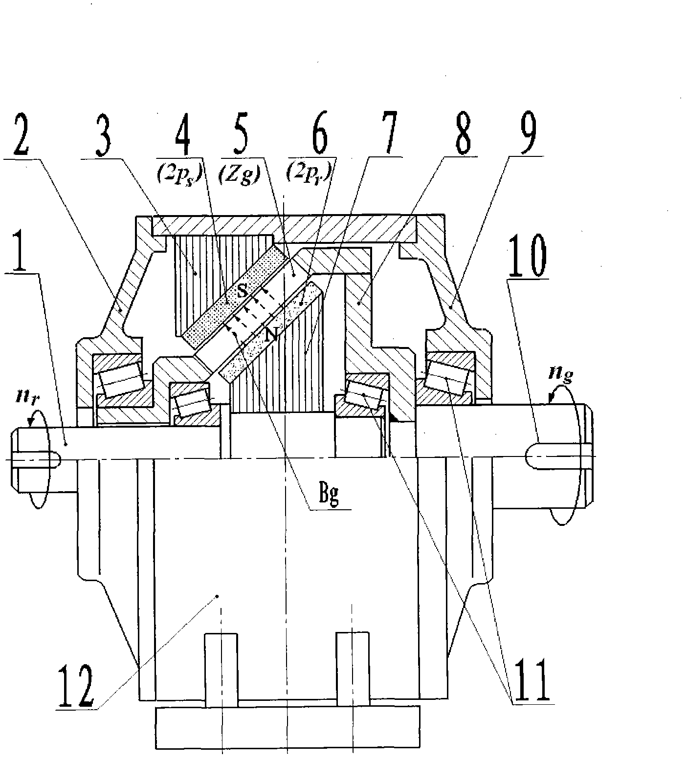
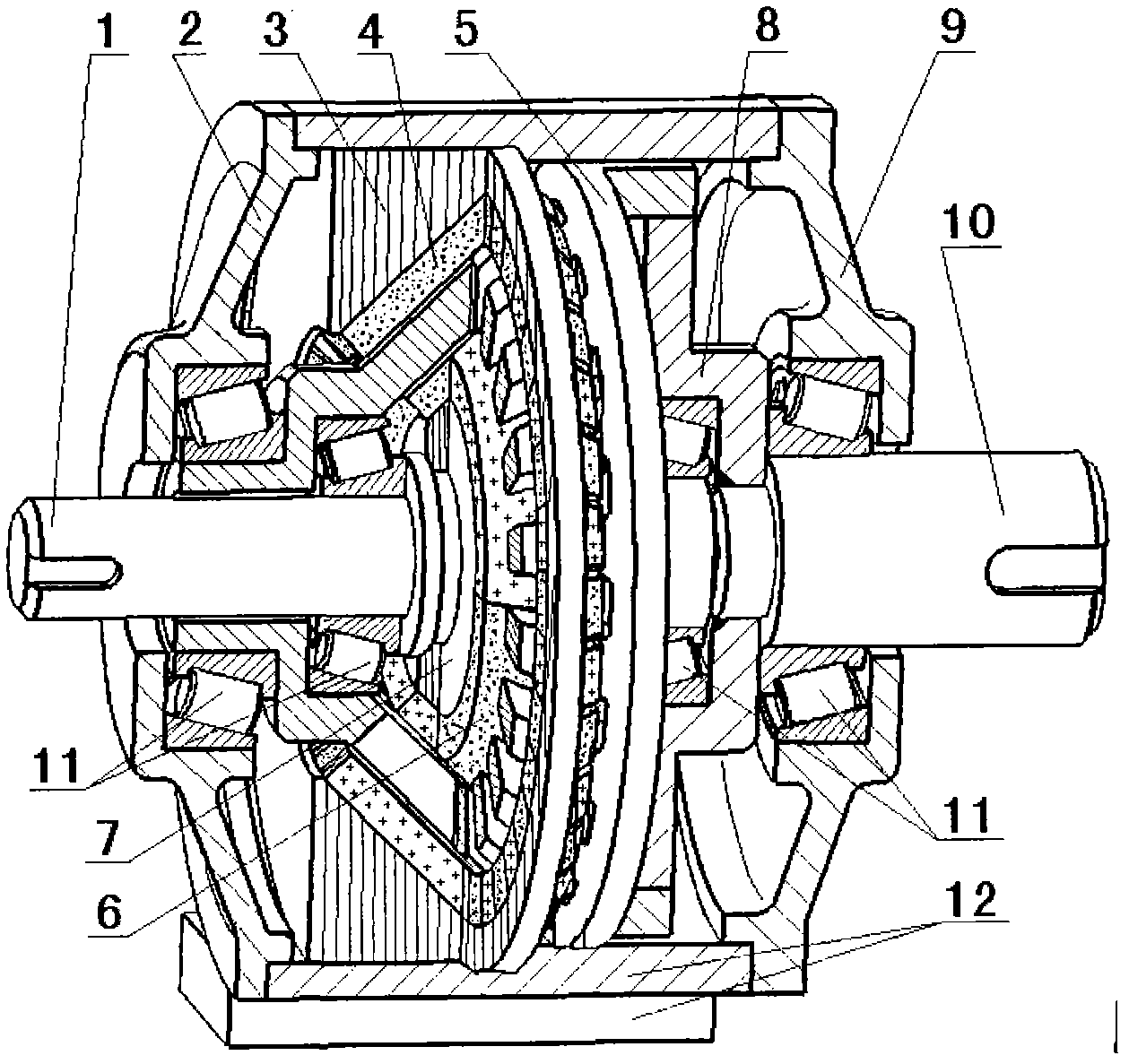
[0026] figure 1 The illustrated embodiment is a half-sectional view of the planar structure of a novel magnetic transmission helical gear pair with an oblique air gap magnetic field according to the present invention, figure 2 It is a composite sectional view of a three-dimensional structure of a novel magnetic transmission helical gear pair with an oblique air gap magnetic field described in the present invention. In this embodiment, the number of magnetic poles of the driving wheel is 2p r = 4 poles, the number of stator poles is 2p s = 34 poles, the number of teeth of the ferromagnetic grid of the driven wheel Zg = 19, the speed transmission ratio Its internal structural relationship features are as follows:

[0027] 1. The magnetic transmission helical gear pair of the new oblique air gap magnetic field is distributed with 2p r An outer c...


PUM


Abstract

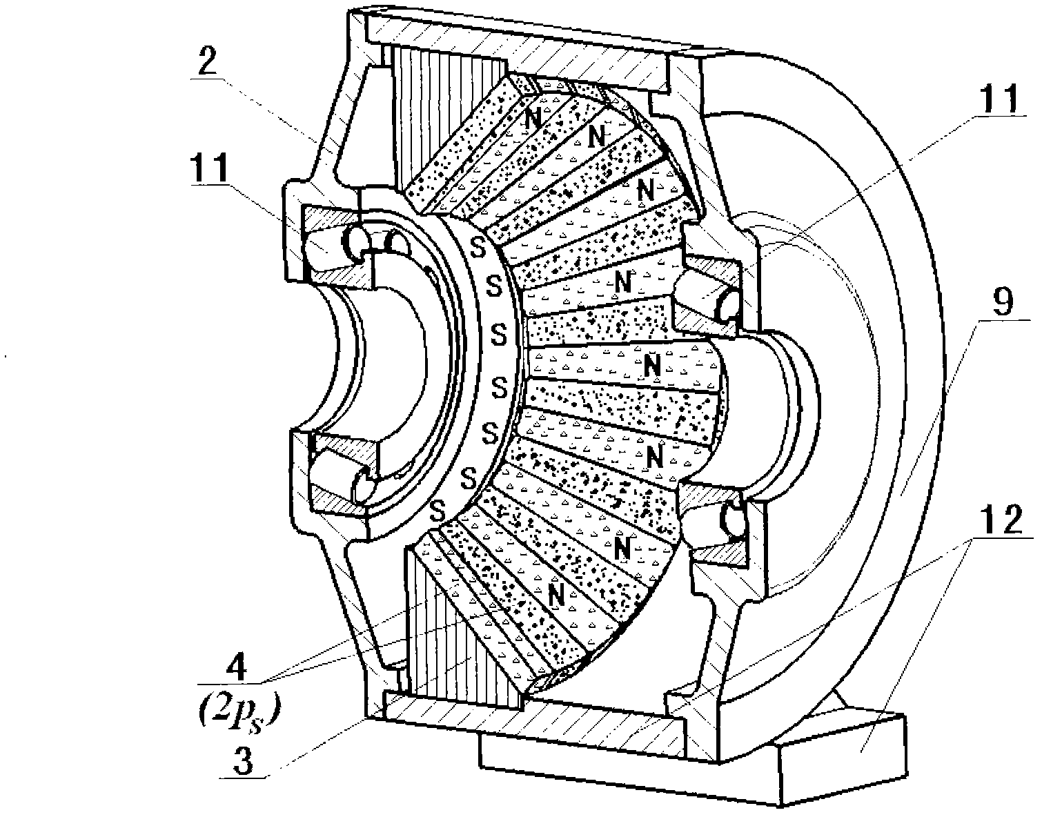
A novel magnetic drive oblique gear pair with an oblique air-gap magnetic field can be widely applied to the industrial drive field of wind power generation, electric cars, ship drive and the like with the requirement of direct driving. The novel magnetic drive oblique gear pair is characterized in that the inner hole of a stator of the magnetic drive oblique gear pair is conical internally; 2ps of stator permanent magnets 4 are distributed on an internally-conical stator iron core 3; a driving gear is conical externally; 2pr of driving gear permanent magnets 6 are distributed on an conical driving gear iron core 7; conical hollow driven gear ferromagnetic grids 5 for modulating the action of a space oblique air-gap magnetic field are mounted between the driving gear permanent magnets 6 and the stator permanent magnets 4; conical space oblique air gaps in coaxial distribution exist among the conical hollow driven gear ferromagnetic grids 5, the driving gear permanent magnets 6 and the stator permanent magnets 4 so as to form an air-gap magnetic field Bg of the magnetic drive oblique gear pair to pass along the conical space air gaps, thereby forming an oblique magnetic field of the magnetic drive oblique gear pair. During work, the power variable speed drive of the magnetic drive oblique gear pair is realized without mechanical contact and friction by utilizing the principle that N pole and S pole of a permanent magnetic material are attracted to each other based on different polarity.

Description

technical field [0001] The invention is a novel helical gear pair for magnetic transmission with an oblique air gap magnetic field, which can be widely used in wind power generation, electric vehicles, ship drive and other industrial transmission fields requiring direct drive. Background technique [0002] Among the methods for increasing the drag torque, the mechanical gear variable speed transmission is widely used, but the basic form of transmission has not changed for a long time, that is, the transmission is always carried out by the meshing of the two gear teeth of the mechanical gear pair. This brings some indelible problems to the gear transmission, such as mechanical fatigue, friction loss, vibration noise, etc. Although the grease lubrication technology can be used, the above problems still cannot be eradicated, resulting in extremely cumbersome use and maintenance, and the mechanical gear transmission. The theoretical efficiency can only reach 85% at most. The mec...

Claims


Application Information

Patent Timeline
Patent Type & Authority Applications(China)
IPC IPC(8): F16H49/00
Inventor 余虹锦
Owner 余虹锦
Learn More