Inner finned tube condenser

A technology of inner fins and condensers, applied in the field of heat exchange equipment, can solve the problems of hindering the heat exchange of cold and hot materials, damage of components, and decrease of heat exchange coefficient, so as to achieve the effects of improving safety, strengthening heat transfer, and speeding up flow rate.

Inactive Publication Date: 2012-12-19
山东擎雷环境科技股份有限公司
View PDF5 Cites 6 Cited by
  • Summary
  • Abstract
  • Description
  • Claims
  • Application Information

AI Technical Summary

Problems solved by technology

[0002] At present, the most common condenser is usually a shell and tube structure, with small heat transfer area, large and heavy, and non-condensable gas evenly adheres to the tube wall, forming a diaphragm, which hinders the heat exchange between hot and cold materials ; In addition, the tube-

Method used


Image

  • Inner finned tube condenser
  • Inner finned tube condenser

Examples


Embodiment 1

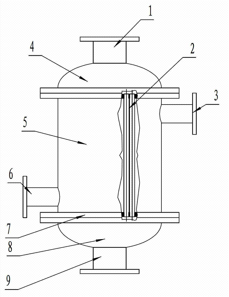
[0015] Embodiment 1, an internal finned tube condenser, including a vertical shell 5, an upper tube box 4 with a tail gas inlet 1, a lower tube box 8 with a condensate outlet 9, a cold water inlet 6, hot water The outlets 3 are respectively located on the lower and upper sides of the shell, and are characterized in that the inner fin type heat exchange tubes 2 are installed between the tube plates at both ends of the shell.

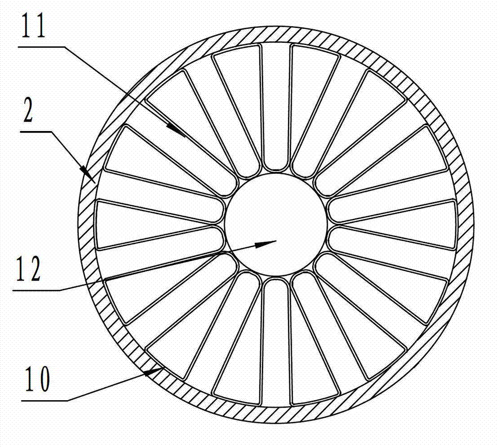
[0016] The structure of the internal fin heat exchange tube is that the center of the heat exchange tube is provided with an inner pin 12, and both ends of the inner pin are provided with sealing plugs. A radial inner fin 11 is installed between the inner pin and the inner wall of the heat exchange tube. Both ends of the inner pin in the middle of the heat exchange tube are provided with sealing plugs.

Embodiment 2

[0017] Embodiment 2, an internal finned tube condenser, comprising a vertical shell 5, an upper tube box 4 with a tail gas inlet 1, a lower tube box 8 with a condensate outlet 9, a cold water inlet 6, hot water The outlets 3 are respectively located on the lower and upper sides of the shell, and are characterized in that the inner fin type heat exchange tubes 2 are installed between the tube plates at both ends of the shell. The structure of the internal fin heat exchange tube is that the center of the heat exchange tube is provided with an internal pin, and both ends of the internal pin are provided with sealing plugs. The U-shaped fins 11 whose arc-shaped top ends are tangent to the inner pin are arranged in a circular array in the heat exchange tube. Two adjacent U-shaped fins are connected to each other at one end close to the inner wall of the heat exchange tube. The infiltrated brazing layer 10 is connected. The U-shaped fin whose inner arc-shaped top end of the heat exc...


PUM


Abstract

The invention discloses an inner finned tube condenser which belongs to heat exchange equipment, and in particular relates to a condenser using an inner finned tube. The inner finned tube condenser comprises a vertical type shell, an upper tube box with a tail gas inlet, and a lower tube box with a condensation water outlet, wherein a cold water inlet and a hot water outlet are respectively located on two upper and lower sides of the shell, and the condenser is characterized in that an inner finned heat exchange tube is mounted between pipe sheets at both ends of the shell. An operation experiment of the heat exchanger shows that after the tail gas is subject to heat exchange, heat is very fully exchanged, the recovery effect, especially for organic solvent, is very good, and the recovery rate is increased by 10% compared with the heat exchanger currently in the market; at the same time the circulation interface of the heat exchanger is relatively large, and no resistance exists behind a vacuum pump; and the heat exchange is very thorough.

Description

Technical field [0001] The invention belongs to heat exchange equipment, especially a condenser using inner finned tubes. Background technique [0002] The most common condenser at present is usually a tubular structure, with small heat exchange area, large volume and heavy, and the non-condensable gas is evenly attached to the tube wall to form a diaphragm, which hinders the heat exchange between hot and cold materials In addition, the tubular heat exchanger has no self-compensation capability, and it is extremely easy to cause damage to the components under frequent hot and cold replacement working conditions. Furthermore, the pipe cannot be disassembled and cleaned to cause fouling, and the heat transfer coefficient decreases year by year. Summary of the invention [0003] In order to overcome the shortcomings of the existing tube-and-tube heat exchangers of small heat exchange area and large volume, the present invention provides an internal finned tube condenser. The interna...

Claims


Application Information

Patent Timeline
IPC IPC(8): F28B1/02F28F1/40
Inventor 龙宗君
Owner 山东擎雷环境科技股份有限公司
Why Eureka
Try Eureka