Transformer substation local discharge positioning method based on electromagnetic antenna array signal processing

A technology of partial discharge and antenna array, applied in the direction of testing dielectric strength, etc., can solve the problems of no solution, uncertain solution, large positioning error, etc. of measurement error equations

Active Publication Date: 2012-12-19
上海迈内能源科技有限公司
View PDF4 Cites 29 Cited by
  • Summary
  • Abstract
  • Description
  • Claims
  • Application Information

AI Technical Summary

Problems solved by technology

In practical applications, when the signal-to-noise ratio is low, it is difficult to calculate the signal delay, which will bring a large positioning error or even make it impossible to locate
The positioning method based on the signal time delay

Method used


Image

  • Transformer substation local discharge positioning method based on electromagnetic antenna array signal processing
  • Transformer substation local discharge positioning method based on electromagnetic antenna array signal processing
  • Transformer substation local discharge positioning method based on electromagnetic antenna array signal processing

Examples


Embodiment

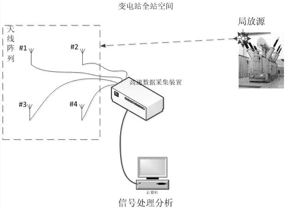
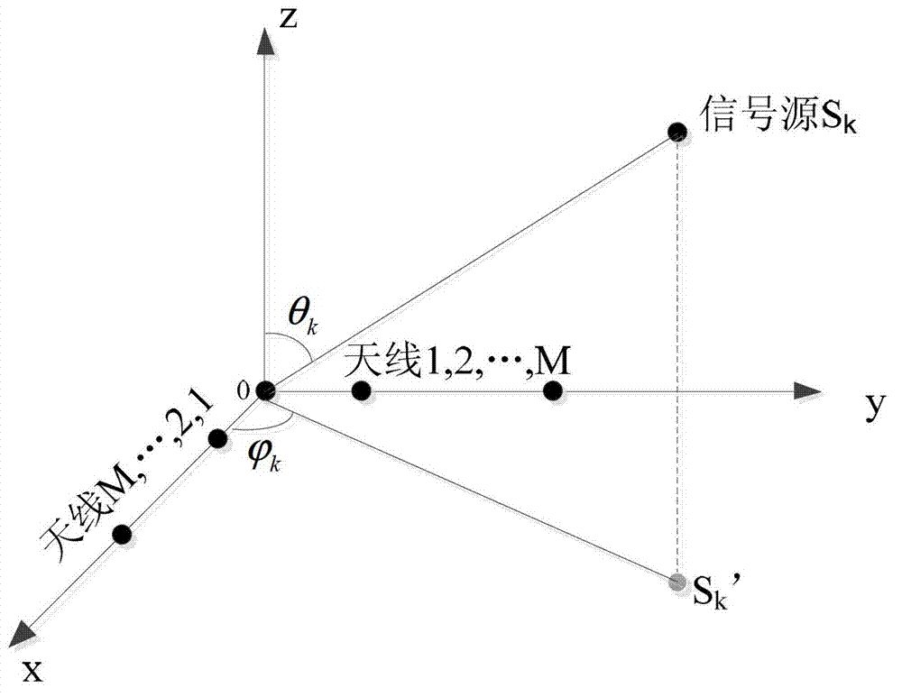
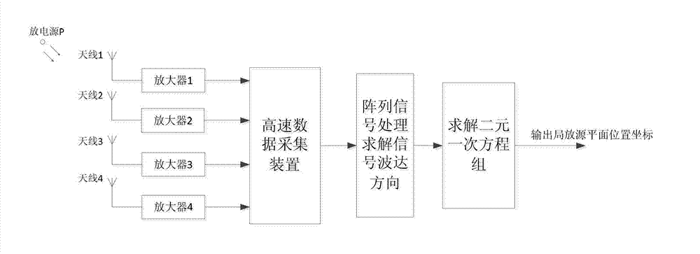
[0050] Place a planar antenna array composed of 4 antennas in the substation, assuming that the projection of the partial discharge source on the antenna array plane is P', first consider the L-shaped array composed of antennas 1, 2, and 4, and take antenna 1 as the coordinate The origin establishes a three-dimensional rectangular coordinate system, and its xoy plane is as follows Figure 4 shown.

[0051] at this time is figure 1 In the case of M=2, K=1, and the observed signal is a real signal. The azimuth of PD source according to the calculation is given below Further steps to obtain the position of the PD source:

[0052] Step 1: For the signals observed by antennas 1, 2, and 4, calculate C according to equations (9)-(12) 1 、C 2 、C 3 and C 4 , and construct the matrix: C=(C 1 ,C 2 ,C 3 ,C 4 ) T ;

[0053] Step 2: Since K=1, calculate the matrix R C =CC H The eigenvector corresponding to the largest eigenvalue of is the matrix E shown in formula (15).

[...


PUM

PropertyMeasurementUnit
Bandwidthaaaaaaaaaa

Abstract

The invention discloses a transformer substation local discharge positioning method based on electromagnetic antenna array signal processing. The transformer substation local discharge positioning method is finished by a local discharge detection device, and the local discharge detection device comprises an omnidirectional antenna array, a built-in amplifier, a super-high-speed data sampling unit and a data processing unit which are mounted in a transformer substation. The positioning method comprises the steps as follows: constructing a matrix according to a concept of working out a signal wave arrival direction by a rotation invariant technology based on L-shaped antenna array signal processing; obtaining an azimuth angle of a local discharge source arriving at an antenna; and finishing planar location of the local discharge source of the transformer substation. A time delay sequence of a signal does not need to be calculated, so that the requirement on a sampling rate of an acquisition system can be lowered; and a plane coordinate of the local discharge source is obtained by working out a linear cross point in two wave arrival directions, namely working out a linear equation set in two unknowns, so that calculation of a nonlinear equation set is avoided.

Description

technical field [0001] The invention belongs to the technical field of insulation monitoring of high-voltage power equipment, and relates to a substation partial discharge positioning method based on electromagnetic wave antenna array signal processing. Background technique [0002] Partial discharge is not only a symptom and manifestation of insulation deterioration, but also the cause of further insulation deterioration. Therefore, partial discharge monitoring has become an effective means to detect insulation defects in power equipment in time and avoid insulation breakdown failures. [0003] The positioning of the partial discharge position is helpful to formulate a targeted maintenance treatment plan, reduce power outage time, and improve maintenance efficiency. Ultra-high-frequency electromagnetic waves have the advantages of strong anti-interference, high sensitivity and stable propagation speed, and their application in partial discharge location and fault diagnosis ...

Claims


Application Information

Patent Timeline
IPC IPC(8): G01R31/12
Inventor 侯慧娟盛戈皞刘亚东张天辰江秀臣
Owner 上海迈内能源科技有限公司
Why Eureka
Try Eureka