
Visual computing-based optical field imaging device and method

A light-field imaging and light-field image technology, applied in color TV parts, TV system parts, TVs, etc. Insufficient flexibility and other problems, to achieve the effect of highlighting creativity and practicality, eliminating blind spots of visual perception, and improving imaging quality

Active Publication Date: 2012-12-19
INST OF AUTOMATION CHINESE ACAD OF SCI
View PDF28 Cites 56 Cited by
  • Summary
  • Abstract
  • Description
  • Claims
  • Application Information

AI Technical Summary

Problems solved by technology

[0007] Light field imaging technology has a great advantage in increasing the depth of field of the image, and the effect of refocusing the foreground and background of the image is satisfactory, but there are still some problems when it is directly applied to the visual perception scene. First, due to the spatial resolution and angle resolution Due to the contradictory relationship between the existing light field imaging devices, there is generally a problem of low image spatial resolution; secondly, the imaging devices that only rely on the existing light field acquisition form still have certain limitations in depth estimation and 3D imaging; at the same time, the current Light field imaging technology has not yet considered the image wide dynamic requirements in the advanced visual perception environment; in addition, the acquisition and editing of the region of interest is currently based on the geometric position modeling of the camera, which is still insufficient in accuracy and flexibility, and in the process of improving the depth of field Medium and heavy focusing points need to be manually specified, which cannot meet the actual needs of advanced visual cognition tasks

Method used


Image

  • Visual computing-based optical field imaging device and method
  • Visual computing-based optical field imaging device and method
  • Visual computing-based optical field imaging device and method

Examples


Embodiment Construction

[0038] In order to make the object, technical solution and advantages of the present invention clearer, the present invention will be described in further detail below in conjunction with specific embodiments and with reference to the accompanying drawings.

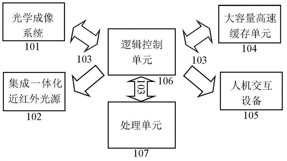
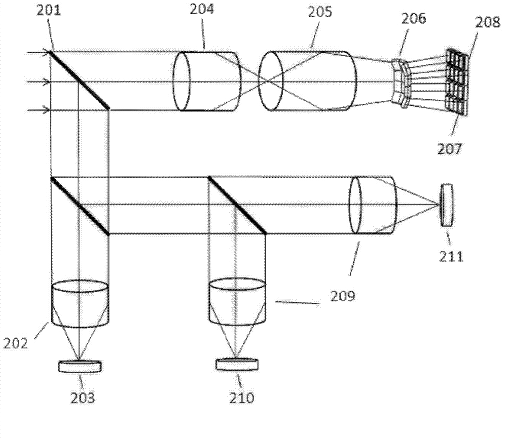
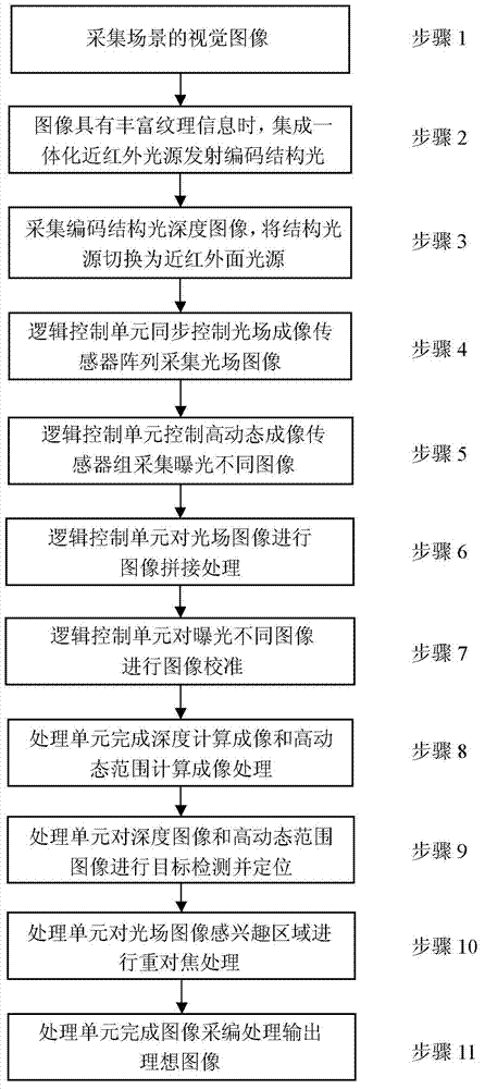
[0039] The invention is oriented to the development frontier of advanced visual computing disciplines and the major strategic needs of the national economy, society and public security fields such as the Internet of Things, video surveillance, biometrics, and intelligent transportation, and breaks through the traditional smooth imaging method in imaging depth of field, dynamic range, depth perception, etc. In order to solve the technical bottlenecks in the field, an intelligent light field imaging device based on the "computing + imaging" interactive win-win mode is proposed, which is dominated by light field imaging, supplemented by depth perception and high dynamic range imaging, and realizes intelligent visual perception...


PUM


Abstract

The invention discloses a visual computing-based optical field imaging device and method. The visual computing-based optical field imaging device comprises an optical imaging system, an integrated near-infrared light source, a data transmission module, a high-capacity cache unit, a human-machine interaction device, a logic control unit and a processing unit. The invention provides an optical field imaging device based on a computing and imaging interactive mutual-beneficial mode; and with optical field imaging as the leading and deep perception and high-dynamic range imaging as the assistance, visual perception intelligent and visual cognition precision are realized, novel visual information with characteristics of large depth-of-field, wide dynamic range, actual three dimension, high resolution and capability of collecting and editing is obtained, and accuracy and robustness of a visual computing task are improved through data innovation of a visual perception source; and the optical field imaging device is widely applied to the fields of internet of things, security monitoring and control, biological recognition, intelligent transportation system, aerial remote sensing, digital medical treatment, animation media and the like.

Description

technical field [0001] The present invention relates to technical fields such as computer vision, optical engineering, computer graphics, pattern recognition, artificial intelligence, etc., especially a light field imaging device and method for visual computing, which can realize large depth of field, wide dynamic range, true three-dimensional, high resolution , Light field imaging that will be edited. Background technique [0002] Vision is the most important source of information for humans to perceive the world. Visual computing attempts to endow machines with the ability to automatically obtain high-level semantic knowledge of physical scenes from image and video data. Economic and social development has important practical value. Solving behavior and event analysis in complex environments in real scenes is an important challenge in the field of visual computing. Traditional imaging devices follow the imaging principle of directly acquiring two-dimensional image inform...

Claims


Application Information

Patent Timeline
IPC IPC(8): H04N5/232H04N13/02G02B27/22
Inventor 谭铁牛孙哲南侯广琦秦娅楠
Owner INST OF AUTOMATION CHINESE ACAD OF SCI
Learn More