
Control method for upward and downward head bending of plate blank

A control method and the technology of warping buckle heads, which are applied in the direction of rolling mill control devices, metal rolling, manufacturing tools, etc., can solve problems such as high labor intensity, production stagnation, and different control effects, and achieve flatness improvement, easy maintenance, The effect of high measurement accuracy

Active Publication Date: 2012-12-26
BAOSHAN IRON & STEEL CO LTD
View PDF10 Cites 26 Cited by
  • Summary
  • Abstract
  • Description
  • Claims
  • Application Information

AI Technical Summary

Problems solved by technology

Because this method requires manual operation, it is labor intensive and requires workers to always pay attention to the warpage of the slab. Once negligent, it will cause production stagnation and even damage equipment
In addition, due to differences in the professional skills of workers, different operating skills have different control effects.

Method used


Image

  • Control method for upward and downward head bending of plate blank
  • Control method for upward and downward head bending of plate blank
  • Control method for upward and downward head bending of plate blank

Examples


Embodiment 1

[0154] Embodiment 1 (head warping situation):

[0155] refer to Figure 10 , the current slab thickness Δh = 15cm, the lower roll rolling speed V = 2.3m / s in this pass. According to the steel type and pass before the slab is rolled, the speed difference setting value obtained from the layer file is ΔQ old = 4%, which means that the speed of the lower roll of the slab is 4% faster than that of the upper roll, and the slab warps upward after the current rolling pass, such as figure 1 shown in . The image measurement function separates the edge of the upper surface of the slab from the background, the sampling interval is 1.5m, and the number of sampling points is 20 to represent the warping curve of the slab head. The coordinates of these 20 points are as follows Figure 5 As shown in , the specific values ​​are as follows:

[0156] Form 2

[0157] serial number

1

2

3

4

5

6

7

8

9

10

X=

...

Embodiment 2

[0204] Embodiment 2 (discount situation):

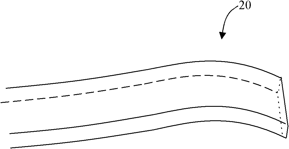
[0205] like figure 2 As shown, the current slab thickness Δh=19.7cm, the rolling speed of the lower roll V=2.3m / s, and the speed difference setting value obtained from the layer file according to the steel type and pass before rolling is ΔQ old = 0%, it means that there is no speed difference between the upper and lower rolls, and the slab is bent downward after rolling in the current pass, such as figure 2 shown in . The image measurement function separates the edge of the upper surface of the slab from the background, and uses 20 sampling points to represent the warping curve of the slab head, and the sampling interval is 1.5m. The coordinates of these 20 points are as follows Image 6 As shown, the specific values ​​are as follows:

[0206] serial number

1

2

3

4

5

6

7

8

9

10

X=

0

7.8

15.5

23.2

31

38.7

46....


PUM

PropertyMeasurementUnit
Thicknessaaaaaaaaaa
Thicknessaaaaaaaaaa

Abstract

The invention discloses a control method for upward and downward head bending of a plate blank, and the control method comprises the steps that a head shape curve of the plate blank and a plurality of sampling sites are collected by CCD (charge coupled device) camera equipment; a cubic polynomial curve is used for fitting according to the sampling sites; the maximum monotone interval of the curve close to the head of the plate blank is obtained to judge the upward or downward head bending; and quantification is conducted; the arc length deviation value of the upper and lower surfaces between the head end point and the tail end point of the plate blank is calculated; a speed difference adjustment value of upper and lower rolls in the pass is calculated; and a new speed difference is decided according to the speed difference adjustment value. The control method for the upward and downward head bending of the plate blank is high in measurement accuracy and easy to maintain, a set value of the speed difference can be adjusted automatically according to the buckling condition of the rolled plate blank, and the straightness of the rolled plate blank can be improved greatly.

Description

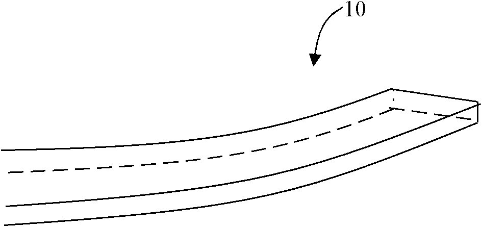
technical field [0001] The invention relates to hot-rolled strip slab rolling, in particular to a method for controlling slab warping for eliminating slab warping. Background technique [0002] In the hot rolling process of the strip steel slab, the head bending phenomenon often occurs after the slab is rolled in one pass, and the upward bending of the head is called head warping, such as figure 1 As shown in 10, the downward bending of the head is called buckling, such as figure 2 Shown in 20. The main reason for warped buckles is asymmetric deformation during rolling. The main factors causing asymmetric deformation include: temperature distribution of slab, elevation of rolling line, diameter of upper and lower work rolls, rolling speed of upper and lower rolls, bite The entry angle, the surface friction coefficient of the upper and lower rolls, and the reduction amount, etc. The bending of the slab head is the result of the combined effect of these factors. The occur...

Claims


Application Information

Patent Timeline
IPC IPC(8): B21B37/68B21B38/00
Inventor 沈际海张健民张先念
Owner BAOSHAN IRON & STEEL CO LTD
Learn More