Human-simulated mechanical arm in seven degrees of freedom

A technology of manipulators and degrees of freedom, applied in the field of manipulators, can solve the problems of heavy manipulators, low load capacity, and low integration, and achieve the effect of light weight, strong load capacity, and high integration

Inactive Publication Date: 2012-12-26
黄刚
View PDF7 Cites 47 Cited by
  • Summary
  • Abstract
  • Description
  • Claims
  • Application Information

AI Technical Summary

Problems solved by technology

[0003] The purpose of the present invention is to provide a humanoid seven-degree-of-freedom mechanical arm to solve the problems of the existing mechanical arm with...

Method used


Image

  • Human-simulated mechanical arm in seven degrees of freedom
  • Human-simulated mechanical arm in seven degrees of freedom
  • Human-simulated mechanical arm in seven degrees of freedom

Examples


specific Embodiment approach 1

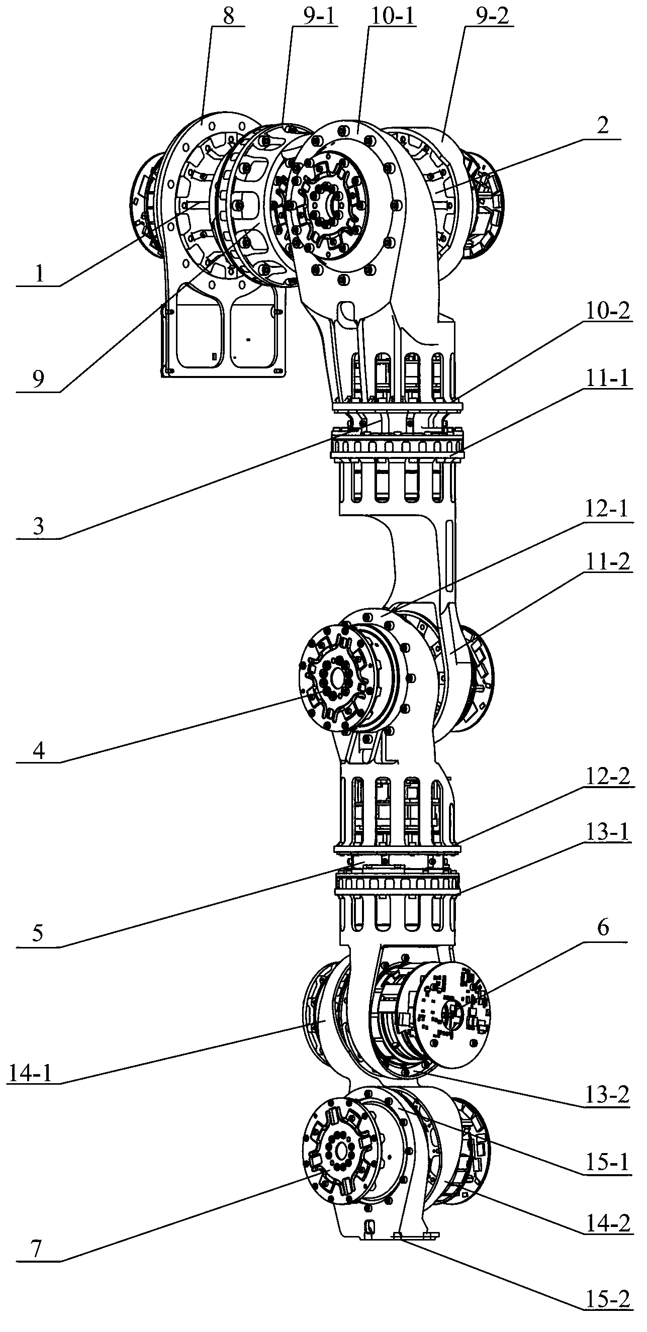
[0008] Specific implementation mode one: combine figure 1 , figure 2 , Figure 5a-5c as well as Figure 6a-Figure 6f Explain that a humanoid seven-degree-of-freedom mechanical arm in this embodiment includes a mechanical arm base 8, wires, seven arm levers, and seven mechatronic modular rotary joints; the seven The first boom 9, the second boom 10, the third boom 11, the fourth boom 12, the fifth boom 13, the sixth boom 14 and the seventh boom 15, the seven The mechatronic modular rotary joints are the first shoulder joint 1, the second shoulder joint 2, the first elbow joint 3, the second elbow joint 4, the first wrist joint 5, the second wrist joint 6 and the third wrist joint 7. The input end 1-1 of the first shoulder joint 1 is fixedly connected to the base 8 of the mechanical arm, the output end 1-2 of the first shoulder joint 1 is fixedly connected to the input end 9-1 of the first arm 9, and the first The output end 9-2 of the arm lever 9 is fixedly connected with ...

specific Embodiment approach 2

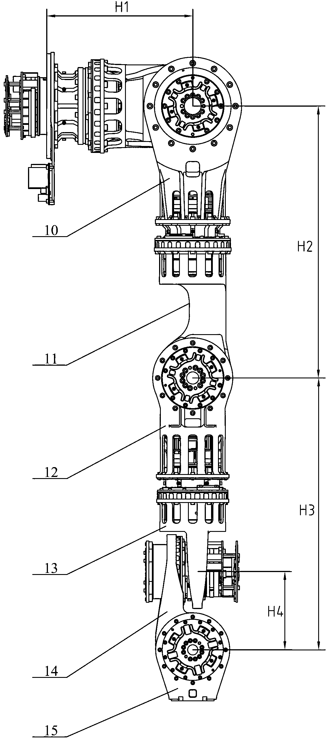
[0009] Specific implementation mode two: combination figure 1 , figure 2 , Figure 6a , Figure 6c and Figure 6f Explain that the distance H1 between the manipulator base 8 and the rotation axis 2-3 of the second shoulder joint 2 in this embodiment is 220 mm, and the rotation axis 2-3 of the second shoulder joint 2 and the rotation axis 2 of the second elbow joint 4 The distance H2 of 4-3 is 400mm, the distance H3 between the rotation axis 4-3 of the second elbow joint 4 and the rotation axis 7-3 of the third wrist joint 7 is 400mm, and the rotation axis 6-3 of the second wrist joint 6 and The distance H4 between the rotation axes 7-3 of the third wrist joint 7 is 115 mm. The undisclosed technical features in this embodiment are the same as those in the first embodiment.

specific Embodiment approach 3

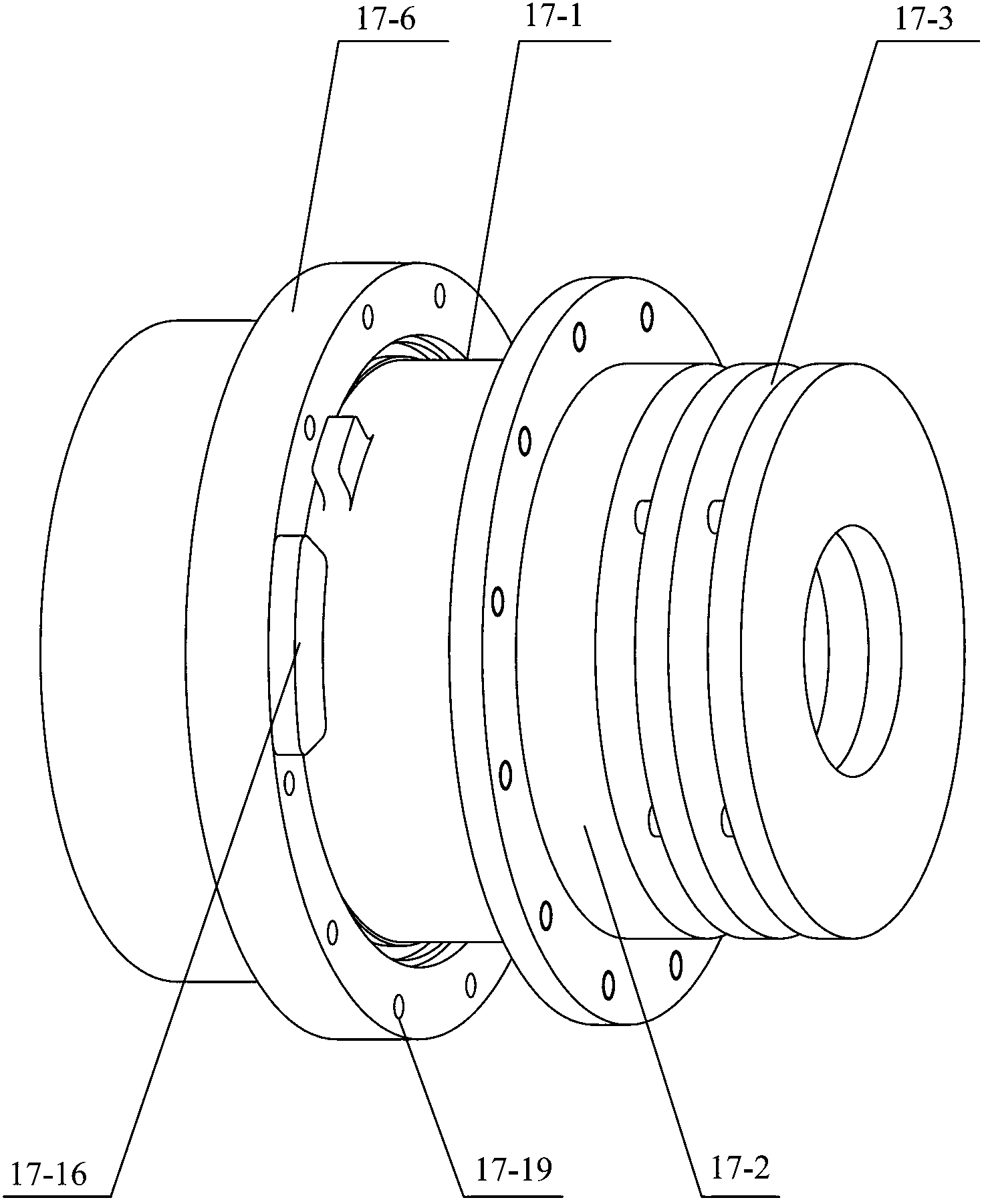
[0010] Specific implementation mode three: combination image 3 and Figure 4 Explain that each mechatronic modular rotary joint in this embodiment includes a mechanical system 17-1, a power-off brake 17-2, an electrical system 17-3, and a sensor system 17-4, which are sequentially connected and integrated. The structure is: the mechanical system 17-1 includes the joint fixed end 17-5, the joint output end 17-6, the joint transmission device 17-7, the cross bearing 17-8, the first deep groove ball bearing 17-9, the second deep groove ball bearing Groove ball bearing 17-10 and harmonic reducer 17-11, one end of the joint fixed end 17-5 is arranged in the joint output end 17-6, and the joint fixed end 17-5 and the joint output end 17-6 pass through a cross The cross bearing 17-8 is connected, the joint transmission device 17-7 is arranged in the joint fixed end 17-5, and the first deep groove ball bearing 17-9 and the second joint transmission device 17-7 are passed between the...


PUM


Abstract

The invention discloses a human-simulated mechanical arm in seven degrees of freedom and belongs to the robot field, aiming at solving the problems that the existing mechanical arm is heavy in weight, low in loading capacity, poor in flexibility, low in integration level, and the working capacity of a robot system end effector is limited to be improved. According to the human-simulated mechanical arm, a first shoulder joint is fixedly connected with a base and a first arm lever of the mechanical arm; the first arm lever is fixedly connected with a second arm lever through a second shoulder joint; the second arm lever is fixedly connected with a third arm lever through a first elbow joint; the third arm lever is fixedly connected with a fourth arm lever through a second elbow joint; the fourth arm lever is fixedly connected with a fifth arm lever through a first wrist joint; the fifth arm lever is fixedly connected with a sixth arm lever through a second wrist joint; the sixth arm lever is fixedly connected with a seventh arm lever through a third wrist joint; the seventh arm lever is fixedly connected with an end effector of the mechanical arm; a rotational axis of the second shoulder joint and a rotational axis of the second elbow joint are in space parallel arrangement; and a rotational axis of the second wrist joint is in orthogonal arrangement with a rotational axis of the third wrist joint. The human-simulated mechanical arm is used for realizing the connection between a robot system main body and the end effector.

Description

technical field [0001] The invention relates to a mechanical arm applied to a humanoid robot system, which belongs to the field of robots. Background technique [0002] The manipulator is an important tool to realize the connection between the main body of the robot system and the end effector. The range of motion and load capacity of the manipulator directly affect the working ability of the robot end effector. In recent years, the rapid development of service robots, space robots and special operation robots has put forward higher requirements for the performance of the manipulator. The seven-degree-of-freedom robotic arm has gradually become a research hotspot in the field of robotics due to its good operational flexibility and obstacle avoidance ability. At present, the robot astronaut R2 jointly developed by NASA and General Motors (GM) has officially started working on the space station. The degree of freedom configuration of the DEXARM manipulator is not conducive t...

Claims


Application Information

Patent Timeline
IPC IPC(8): B25J18/04B25J17/02
Inventor 黄刚
Owner 黄刚
Why Eureka
Try Eureka