Underground pipeline plane and cross section integration showing method

A technology of underground pipelines and plane display, applied in the directions of maps/plans/charts, instruments, educational appliances, etc., can solve problems such as leakage, increased workload, and low safety factor

Inactive Publication Date: 2014-09-24
XIAN MEIHANG INFORMATION IND
View PDF4 Cites 0 Cited by
  • Summary
  • Abstract
  • Description
  • Claims
  • Application Information

AI Technical Summary

Problems solved by technology

[0004] First, the positioning accuracy is low: because the ground reference object is used to locate the underground pipeline against the map, the experience of the construction personnel dominates, and only a rough pipeline direction line can be formed, and its positioning accuracy is seriously insufficient;
[0005] Second, the positioning efficiency is low: due to the inability to perform high-precision positioning, the construction personnel can only use the method of tentative drilling to find the target pipeline, the workload is obviously increased, and the efficiency is low;
[0006] Third, the safety factor is low: the paper map cannot clearly show the environment where the bottom line pipelines are located. "Finding mistakes", in case of special pipelines such as natural gas, will cause safety accidents such as leakage or even explosion
[0007] In summary, the existing underground pipeline display methods are backward in technology and low in positioning accuracy, which seriously restricts the construction progress of underground pipelines

Method used


Image

  • Underground pipeline plane and cross section integration showing method
  • Underground pipeline plane and cross section integration showing method

Examples


Embodiment Construction

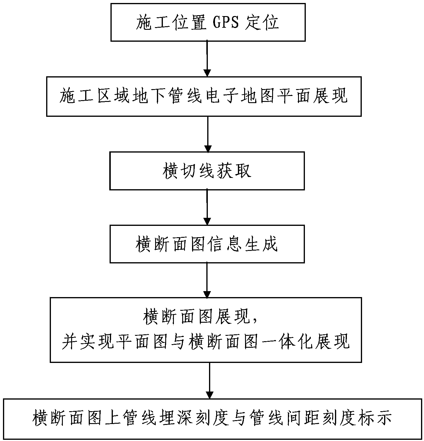
[0052] Such as figure 1 An integrated presentation method of underground pipeline plane and cross-section is shown, including the following steps:

[0053] Step 1. GPS positioning of the construction location: use the GPS measuring device to locate the current construction location, and then transmit the geographic location information of the current construction location measured by the GPS measuring device to the data processor.

[0054] In this embodiment, when the geographic location information of the current construction location obtained by the GPS measuring device is transmitted to the data processor, it is transmitted through a data transmission interface, a wireless communication network or the Internet.

[0055] The geographic location information of the current construction location measured by the GPS measuring device is the geographic coordinates of the current construction location. Among them, the geographic coordinates are spherical coordinates that represen...


PUM


Abstract

The invention discloses an underground pipeline plane and cross section integration showing method comprising the following steps: (1) locating a construction position through a global positioning system (GPS), (2) showing an electronic map plane of underground pipelines of a construction area, (3) obtaining a transverse cutting line and using a data processor to automatically generate the transverse cutting line, (4) generating transverse section graph information: the data processor automatically judges all the underground pipelines which intersect with the transverse cutting line, calculates intersecting positions between each intersecting pipeline and the transverse cutting line, and sends the intersecting positions between each intersecting pipeline and the transverse cutting line and the buried depth of each intersecting pipeline to a display terminal, (5) showing a transverse section graph: a plane graph and a transverse section graph of an electronic map of the underground pipelines are shown in an integral mode, and the plane graph and the transverse section graph are respectively located on the upper side and the lower side of each transverse cutting line. The underground pipeline plane and cross section integration showing method is convenient to operate, fast in response speed, visual in integral showing and high in practical value. Moreover, the underground pipeline plane and cross section integration showing method can provide accurate and effective engineer information for city municipal construction, and underground pipe network projects and construction.

Description

technical field [0001] The invention belongs to the technical field of electronic geographic information processing, and in particular relates to an integrated display method of underground pipeline plane and cross section. Background technique [0002] Nowadays, with the rapid development of social economy, urban construction is changing with each passing day, and urban underground pipelines are used as basic municipal facilities, forming an underground pipeline network system composed of water supply and drainage pipelines, heat pipelines, gas pipelines, etc. The construction and post-maintenance of the underground pipeline network are directly related to the construction progress and operating efficiency of municipal facilities. However, due to the special situation of "invisible and intangible" underground pipelines, the difficulty and workload of post-maintenance of underground pipelines increases. In the event of a sudden pipeline accident, if the distribution of under...

Claims


Application Information

Patent Timeline
Patent Type & Authority Patents(China)
IPC IPC(8): G09B29/00G09B29/10
Inventor 雷国锋周晓龙吴军荣
Owner XIAN MEIHANG INFORMATION IND
Why Eureka
Try Eureka