Flexible replaceable screw thread pair driving ultrasonic motor

An ultrasonic motor, screw pair technology, applied in the direction of generators/motors, piezoelectric effect/electrostrictive or magnetostrictive motors, electrical components, etc. and other problems, to achieve the effect of improving output performance, promoting practical process, and enriching reliability.

Inactive Publication Date: 2012-12-26
HARBIN INST OF TECH
View PDF17 Cites 20 Cited by
  • Summary
  • Abstract
  • Description
  • Claims
  • Application Information

AI Technical Summary

Problems solved by technology

[0004] Judging from the implementation of the threaded pair driven ultrasonic motor in the existing disclosed invention, the threaded driving part on the stator is processed as a whole with the stator, and the stator and the threaded output shaft are mostly connected and driven by a single paired threaded pair. The output performance is single and lacks flexibility, which cannot meet the needs of the growing diversification of motor applications; in addition, since the screw pair drive ultrasonic motor mainly adopts the thread pair transmission form, the matching material, structural form and The size parameters have a great influence on the output performance of the motor, such as output force / torque, output speed, output power, output efficiency, and the axial runout and positioning accuracy of the motor during operation.

Method used


Image

  • Flexible replaceable screw thread pair driving ultrasonic motor
  • Flexible replaceable screw thread pair driving ultrasonic motor
  • Flexible replaceable screw thread pair driving ultrasonic motor

Examples


specific Embodiment approach 1

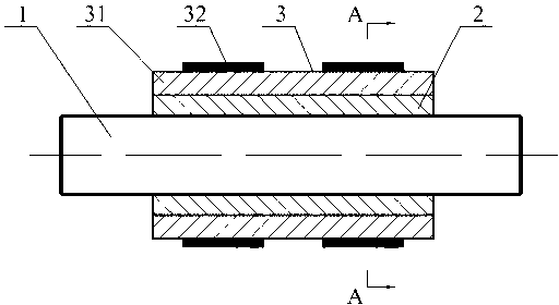
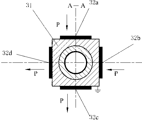
[0035] Specific implementation mode one: see Figure 1 to Figure 8 , a flexible and replaceable screw drive ultrasonic motor, the ultrasonic motor includes a screw output shaft 1, a replaceable screw drive element 2 and an ultrasonic excitation vibrator 3, the shape of the replaceable thread drive element 2 is cylindrical, and the ultrasonic excitation vibrator 3. It consists of an excited body 31 and at least four exciting elements 32. At least four flat sides or grooves with a symmetrical structure and a square orientation are uniformly processed on the peripheral side of the excited body 31 (such as figure 2 and Figure 8 The structure of the groove makes the structure of the ultrasonic excitation vibrator 3 more compact, the number of the excitation element 32 is the same as that of the flat side or the groove, and an excitation element 32 is consolidated on each flat side or in the groove (by cold welding or ring Oxygen resin glue consolidation), the outer surface of ...

specific Embodiment approach 2

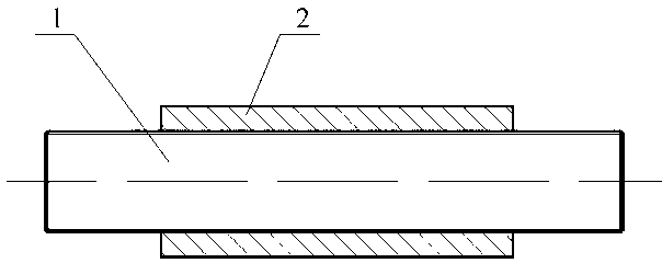
[0042] Specific implementation mode two: see Figure 9 to Figure 16 , a flexible and replaceable threaded auxiliary driving ultrasonic motor, the ultrasonic motor includes a threaded output shaft 1, an ultrasonic excitation vibrator 3 and two replaceable threaded auxiliary driving elements 2, the shape of the replaceable threaded auxiliary driving element 2 is cylindrical, and the ultrasonic The exciting vibrator 3 is composed of an excited body 31 and at least four exciting elements 32, and at least four flat sides or grooves with a symmetrical structure and a square orientation are uniformly processed on the peripheral side of the excited body 31 (such as Figure 10 and Figure 16 , the groove structure makes the structure of the ultrasonic excitation vibrator 3 more compact), the number of the excitation element 32 is the same as that of the flat side or the groove, and one excitation element 32 is consolidated on each flat side or in the groove (by cold welding or ring ...

specific Embodiment approach 3

[0050] Specific implementation mode three: see Figure 17 to Figure 20, a flexible and replaceable threaded auxiliary driving ultrasonic motor, the ultrasonic motor includes a threaded output shaft 1, an ultrasonic excitation vibrator 3 and two replaceable threaded auxiliary driving elements 2, and the shape of the replaceable threaded auxiliary driving element 2 has a cone angle of θ is in the shape of a truncated cone, and the ultrasonic excitation vibrator 3 is composed of an excited body 31 and at least four exciting elements 32, and at least four symmetrical flat sides or Groove, the vibration element 32 has the same number as the flat side or the groove, and one vibration element 32 is fixed on each flat side or in the groove (consolidated by cold welding or epoxy resin), and it is fixed in the groove. The outer surface of the excitation element 32 in the groove is lower than or flush with the side of the excited body 31 where the groove is located, and a mounting hole...


PUM


Abstract

The invention relates to a flexible replaceable screw thread pair driving ultrasonic motor, belonging to the field of ultrasonic vibration application. The performance of the ultrasonic motor is not limited by the material of a screw thread pair and the dimensional parameter of a screw thread structure, the travel error of screw thread pair transmission is eliminated, and the output performance, the application flexibility and the positioning accuracy of the motor are improved. The flexible replaceable screw thread pair driving ultrasonic motor mainly comprises screw thread output shafts, a replaceable screw thread pair driving element and an ultrasonic exciting vibrator. Vibration exciting elements are fixedly bonded on at least four flat side faces or in grooves on the peripheral side faces of a vibrator to be excited. The replaceable screw thread pair driving element is of an integral type or a segmental type and is installed and fixedly bonded in paired installation center holes in a matching manner, and the screw thread output shafts are in thread connection with the replaceable screw thread pair driving element and are paired to output rotary and linear movements. With the flexible replaceable screw thread pair driving ultrasonic motor, the performance output flexibility and the flexible application diversity of this kind of ultrasonic motors are increased, the output characteristic of the motor is improved, and the flexible replaceable screw thread pair driving ultrasonic motor can be applied to the fields of aerospace, automobile industry, medical apparatuses and instruments, optical driving and precision positioning systems and the like.

Description

technical field [0001] The invention belongs to the field of ultrasonic vibration application, and in particular relates to a flexible replaceable screw pair driven ultrasonic motor excited by ultrasonic vibration. Background technique [0002] Based on the ultrasonic driving principle, the ultrasonic motor is driven by the threaded pair of the cylindrical stator bending vibration mode by exciting at least two bending vibration modes in the stator space, and the driving wave is generated by the vibration coupling on the inner surface of the threaded pair of the stator to realize the threaded rod. Output shaft rotation - linear motion output. This type of threaded pair-driven ultrasonic motor has the characteristics of simple structure, high output force / mass ratio density, easy miniaturization, and high positioning accuracy. [0003] At present, there are several typical structures of ultrasonic motors driven by screw pairs: the stator is a polyhedral structure, and the scr...

Claims


Application Information

Patent Timeline
Patent Type & Authority Applications(China)
IPC IPC(8): H02N2/00
Inventor 肖才伟程廷海赵岩
Owner HARBIN INST OF TECH
Why Eureka
Try Eureka