High-capacity ultrasonic crushing and dispersing device

An ultrasonic crushing and large-capacity technology, which is applied in the direction of mixer accessories, mixers, dissolution, etc., can solve problems such as easy to exceed, the emission area should not be too large, and transducer damage, etc., to achieve expanded use range, convenient operation, and uniformity increased effect

Active Publication Date: 2013-01-02
BEIJING UNIV OF CHEM TECH
View PDF7 Cites 16 Cited by
  • Summary
  • Abstract
  • Description
  • Claims
  • Application Information

AI Technical Summary

Problems solved by technology

However, in practical applications, the use of ultrasonic cavitation effects is also subject to many restrictions, mainly due to the influence of ultrasonic power density. Ultrasonic power density is the ratio of the emission power to the emission area. That is, when performing ultrasonic crushing and dispersion, a higher power density is required, which limits the emission area and cannot be too large, and the diameter of the ultrasonic horn cannot be too large, thereby affecting the range of action of the ultrasonic waves.
At the same time, since the ultrasonic generating device of the ultrasonic crushing and dispersing device is mainly a transducer made of electric and magnetostrictive effects, the ultrasonic transducer is a vulnerable part, and if the temperature is too high, the ultrasonic cavitation effect will be reduced, and the transducer may even be damaged. Damaged, when the set power is high and the ultrasonic time is long, the transducer generates a lot of heat, and it is easy to exceed the allowable temperature limit of the transducer
Therefore, the conventional ultrasonic crushing and dispersing device is limited by the heat generation of the transducer and the diameter of the horn, so it is difficult to perform ultrasonic treatment of large quantities of materials for a long time. Solving these two problems can prepare a device that can be used for large-capacity ultrasonic crushing. Dispersion device, which has far-reaching significance for the industrial application of ultrasonic cavitation effect

Method used


Image

  • High-capacity ultrasonic crushing and dispersing device
  • High-capacity ultrasonic crushing and dispersing device
  • High-capacity ultrasonic crushing and dispersing device

Examples


Embodiment Construction

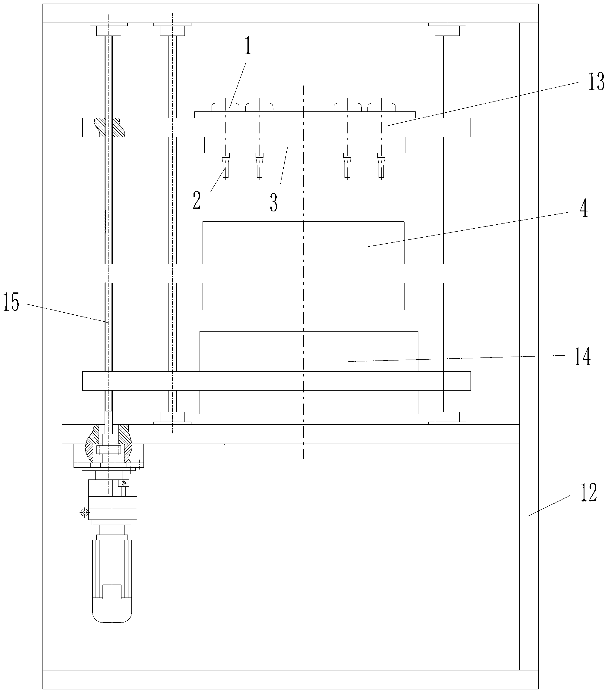
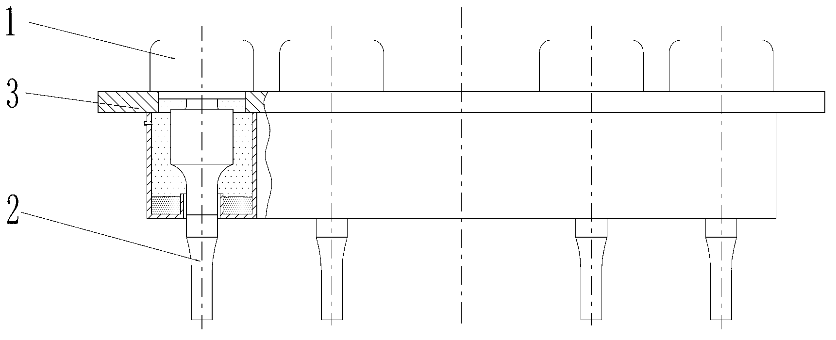
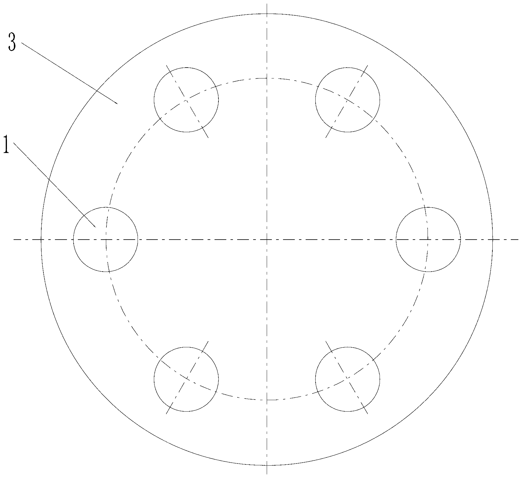
[0029] A large-capacity ultrasonic crushing and dispersing device of the present invention, such as figure 1 As shown, it is mainly composed of an ultrasonic device 13, a material container 4, a magnetic stirring device 14, an automatic lifting device 15, and a frame 12. Among them, such as Figure 4 As shown, the ultrasonic device 13 includes an ultrasonic transducer 1, an ultrasonic horn 2 and a transducer cooling sleeve 3, and the ultrasonic horn 2 is coaxial with the ultrasonic transducer 1 and is installed on the lower end of the ultrasonic transducer 1 , the transducer cooling sleeve 3 is a hollow annular cylinder, the ultrasonic transducer 1 is installed on the transducer cooling sleeve 3 and its vibrating element penetrates the inner cavity of the transducer cooling sleeve 3, and multiple ultrasonic transducers 1 Installed on the transducer cooling sleeve 3 and evenly distributed, such as figure 2 As shown, there is a small gap between the vibrating element and the ...


PUM


Abstract

The invention provides a high-capacity ultrasonic crushing and dispersing device, mainly comprising an ultrasonic device, a material container, a magnetic mixing device, an automatic lifting device and a rack, wherein the ultrasonic device is composed of ultrasonic transducers, an ultrasonic amplitude transformer and a transducer cooling sleeve; the ultrasonic amplitude transformer is coaxial with the ultrasonic transducers and is arranged at the lower ends of the ultrasonic transducers; the transducer cooling sleeve is an annular sleeve with a cavity; the ultrasonic transducers are arranged on the transducer cooling sleeve, and vibrating members penetrate through the inner cavity of the transducer cooling sleeve; and a plurality of ultrasonic transducers are uniformly distributed on the transducer cooling sleeve. A small gap is formed between the vibrating member of each ultrasonic transducer and the transducer cooling sleeve, so that the transducer cooling sleeve cannot be contacted with the vibrating members of the ultrasonic transducers to influence an ultrasonic effect; and a soft material can be filled between the vibrating member of each ultrasonic transducer and the transducer cooling sleeve, so that the transducer cooling sleeve can be sealed on the premise of not influencing the vibrating frequency of the ultrasonic transducers, and a coolant cannot leak to pollute materials.

Description

technical field [0001] The invention relates to a crushing and dispersing device, in particular to an ultrasonic crushing and dispersing device. Background technique [0002] Ultrasound is a sound wave with a frequency higher than 20,000 Hz. It has good directionality and strong penetrating ability. It is easy to obtain concentrated sound energy and has a long distance in water. It can be used for distance measurement, speed measurement, cleaning, welding, gravel, and sterilization. etc. There are many applications in medicine, military, industry and agriculture. Ultrasound is named for its lower frequency limit approximately equal to the upper limit of human hearing. Theoretical research shows that under the condition of the same amplitude, the vibration energy of an object is proportional to the vibration frequency. When the ultrasonic wave propagates in the medium, the vibration frequency of the medium particles is very high, so the energy is very large. Devices that ge...

Claims


Application Information

Patent Timeline
Patent Type & Authority Applications(China)
IPC IPC(8): B01F13/08B01F13/10B01F11/02B01F15/06B01F15/00
Inventor 安瑛王建强丁玉梅杨卫民
Owner BEIJING UNIV OF CHEM TECH
Why Eureka
Try Eureka