
On-site Welding Method of Steel Lining Panel in Nuclear Power Plant

A technology for steel lining and nuclear power plants, applied in arc welding equipment, welding equipment, manufacturing tools, etc., can solve problems such as difficult to guarantee welding quality, heavy welding workload, poor working conditions, etc., to improve welding quality and efficiency, and installation time The effect of shortening, improving ergonomics and quality

Active Publication Date: 2014-10-01
CHINA NUCLEAR IND HUAXING CONSTR
View PDF5 Cites 0 Cited by
  • Summary
  • Abstract
  • Description
  • Claims
  • Application Information

AI Technical Summary

Problems solved by technology

Manual electrode arc welding is a traditional manual welding process, with heavy welding workload, low welding efficiency, large welding deformation, poor working conditions, high labor intensity, difficult to guarantee welding quality, large amount of consumables, and high cost

Method used


Image

  • On-site Welding Method of Steel Lining Panel in Nuclear Power Plant
  • On-site Welding Method of Steel Lining Panel in Nuclear Power Plant
  • On-site Welding Method of Steel Lining Panel in Nuclear Power Plant

Examples


Embodiment 1

[0034] The on-site welding method for the steel lining wallboard of the nuclear power plant in this embodiment adopts argon tungsten arc welding machine and carries out the following steps:

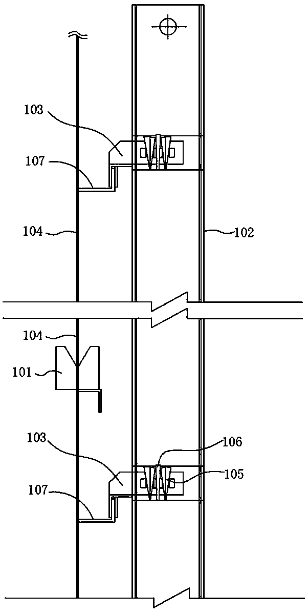
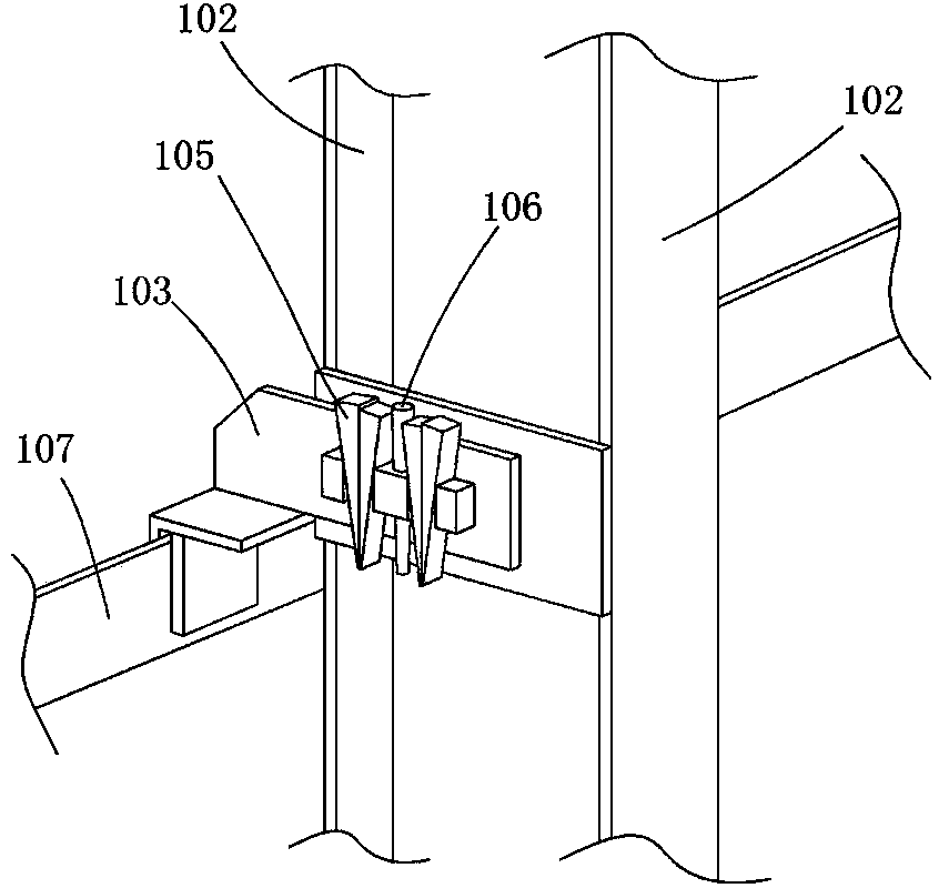
[0035] 1) Assemble the steel-lined panel 104 in place by tooling. Specific as figure 1 with figure 2 As shown, the tooling that present embodiment adopts is guide plate 101, buttress column 102, spectacle plate 103, wedge 105 and bearing pin 106, at first lift and fix buttress column 102 by spectacle plate 103, wedge 105 and pin shaft 106 in the next On the large angle steel 107 of the steel lining wall plate of the first layer; then a pair of guide plates 101 are paired and spot welded on the upper opening of the next layer of wall plate at an interval of about 1m in the circumferential direction; finally, the steel lining wall plate 104 is hoisted, and the upper and lower layers of steel lining wall plates 104 close to each other through the guide plate 101, and through the buttress ...

Embodiment 2

[0049] The on-site welding method of the steel lining panel of the nuclear power plant in this embodiment is basically the same as that in Embodiment 1, except that the main welding process parameters of the automatic full welding in step 3) are different, as shown in Table 2 below:

[0050] Table 2

[0051]

Embodiment 3

[0053] The on-site welding method of the steel lining wall plate of the nuclear power plant in this embodiment is basically the same as that in the first embodiment, except that the main welding process parameters of the automatic full welding in step 3) are different, as shown in Table 3 below:

[0054] table 3

[0055]


PUM


Abstract

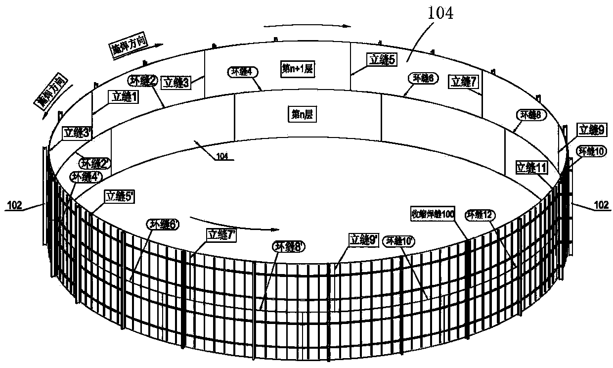
The invention relates to a field welding method for wall boards of a steel lining of a nuclear power plant, belonging to the technical field of building decoration of the nuclear power plant. The method comprises the following steps of: assembling the wall boards of the steel lining in place through a tool and randomly selecting a vertical seam between the wall boards of the steel lining as a shrinkage vertical seam for field final welding; performing spot welding on a vertical seam opposite to the shrinkage vertical seam, next performing spot welding on two circular seams adjacent to the left and right sides of the first vertical seam, then continuously performing spot welding on the two vertical seams adjacent to two first circular seams along the clockwise direction and the anticlockwise direction respectively, performing spot welding on all vertical seams and circular seams at spaced locations along the clockwise direction and the anticlockwise direction respectively from the first vertical seam by analogy, until the final manual spot welding is performed on the shrinkage vertical seam; and repeating the steps to perform automatic full-length welding on all vertical seams and circular seams from the first vertical seam which is subjected to spot welding, until the final automatic full-length welding is performed on the shrinkage vertical seam. According to the method, field mounting of the wall boards of the steel lining of the nuclear power plant is performed by using a tungsten electrode argon arc automatic welding machine, the welding deformation is reduced, and the mounting working efficiency and the quality are improved.

Description

technical field [0001] The invention relates to an installation process for a nuclear power plant steel lining, belonging to the technical field of nuclear power plant building decoration. Background technique [0002] According to the medium and long-term development plan for nuclear power reviewed and approved by the State Council in principle, the proportion of nuclear power in the entire energy structure will reach more than 4% by 2020, and China's nuclear power installed capacity will reach 70 million kilowatts. Our country's nuclear power development policy has developed from a moderate level. Nuclear power is transformed into active development of nuclear power. Each nuclear power construction company will face the challenge of simultaneously undertaking the construction tasks of multiple nuclear power units and the integrated management of multiple projects. In order to actively respond to the challenges of large-scale nuclear power project construction, it is necess...

Claims


Application Information

Patent Timeline
Patent Type & Authority Patents(China)
IPC IPC(8): B23K9/167
Inventor 张科青程小华肖卫华别刚刚陈宝智秦亚林
Owner CHINA NUCLEAR IND HUAXING CONSTR
Learn More