Wave blade-shaped end mill processing method

A processing method and end mill technology, applied in the field of machining tools, can solve the problems of easy loss of service life, not smooth chip removal, large cutting resistance, etc., and achieve the advantages of reduced cutting resistance, smooth chip removal, and improved processing efficiency. Effect

Active Publication Date: 2013-01-02
HARBIN TURBINE
View PDF5 Cites 15 Cited by
  • Summary
  • Abstract
  • Description
  • Claims
  • Application Information

AI Technical Summary

Problems solved by technology

[0003] The purpose of the present invention is to provide a processing method for wave-edged end mills to solve the problem of excessive cutting resistance, insufficient chip removal, unequal grinding, Easy to wear and short service life, making it less efficient

Method used


Image

  • Wave blade-shaped end mill processing method
  • Wave blade-shaped end mill processing method

Examples


specific Embodiment approach 1

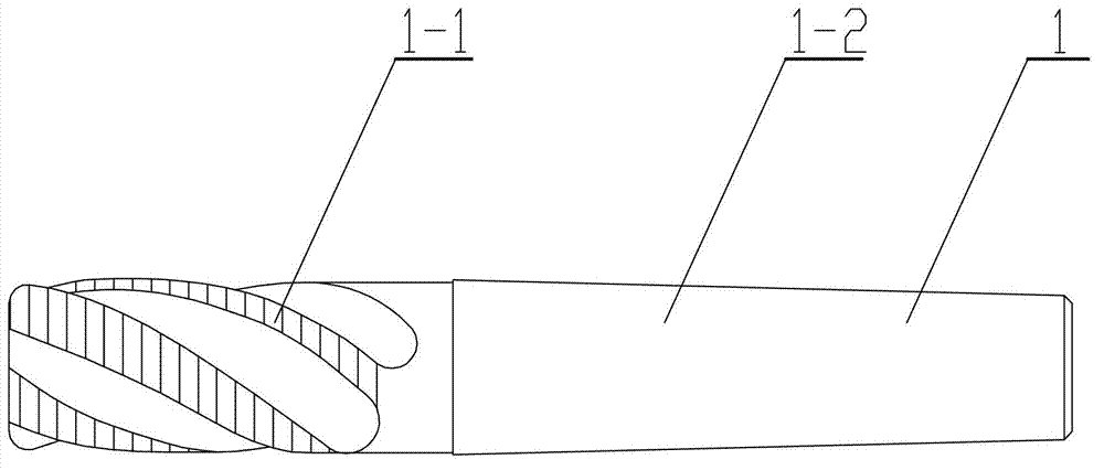
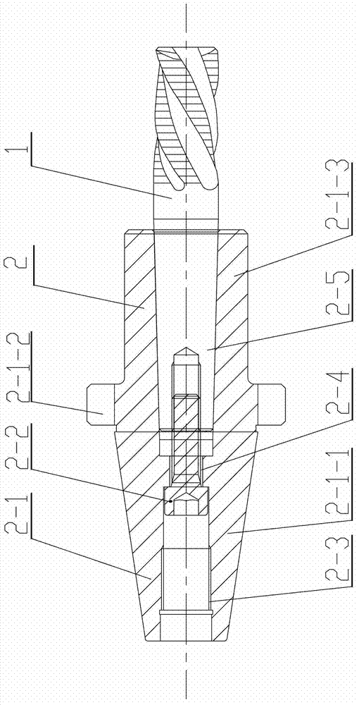
[0018] Specific implementation mode one: combine figure 1 and figure 2 To illustrate this embodiment, the special fixture 2 used in the processing method of wave-blade end mills in this embodiment includes a clamp body 2-1 and a tension screw 2-2, and the clamp body 2-1 is made of a cone 2-1-1, the annular boss 2-1-2 and the cylinder 2-1-3 are sequentially formed and made into an integrated rotary body, the large diameter end of the cone 2-1-1 and the annular boss 2-1 One end of -2 is fixedly connected, and the other end of the annular boss 2-1-2 is fixedly connected with one end of the cylinder 2-1-3, and the inside of the clamp body 2-1 is connected from the small part of the cone 2-1-1. The other end of the diameter end to the cylinder 2-1-3 is sequentially processed with a connected M24 threaded hole 2-3, a Φ18 hole 2-4 and a Mohs No. 4 inner hole 2-5, and the tension screw 2-2 passes through the The M24 threaded hole 2-3 is detachably connected to the clamp body 2-1; ...

specific Embodiment approach 2

[0027] Specific implementation mode two: combination figure 2 This embodiment will be described. In this embodiment, the taper of the shank of the chuck body 2-1 is 7:24. This setting can make the wave-blade end mill 1 be positioned in the spindle hole of the five-axis CNC grinding machine with high precision, which is more conducive to realizing the purpose of the present invention. The other method steps are the same as in the first embodiment.

specific Embodiment approach 3

[0028] Specific implementation mode three: combination figure 2 This embodiment is described. In this embodiment, the tension screw 2-2 is an M16 tension screw. The application of the M16 tension screw in the present invention can achieve the best inventive effect, and the other method steps are the same as those of the specific embodiment 1 or 2.


PUM

PropertyMeasurementUnit
diameteraaaaaaaaaa

Abstract

The invention discloses a wave blade-shaped end mill processing method, and relates to an end mill processing method. The invention aims at solving the problem that the currently processed wave blade-shaped end mill is low in working efficiency in the use process caused by the reasons of being excessive in cutting resistance, unsmooth in chip removal, unequal in grinding, prone to damage and short in service life. The method provided by the invention comprises the following steps of: step 1: turning a milling cutter blank; step 2: milling peripheral teeth, widening back of teeth, and accurately milling with a 38-degree helical angle, wherein the cutting parameters are as follows: the rotation speed is 200r / min, and the feeding is 0.15mm / r; step 3: thermal treatment; step 4: external grinding; step 5: grinding the front angle, the wave blade form and the rear angle by a five-axis numerically controlled grinding machine; and step 6: coating treatment. The method provided by the invention is clear in steps and easy to carry out, in comparison with the conventional wave blade-shaped end mill, the working efficiency of the wave blade-shaped end mill processed by the method is doubled and the service life is improved by 20-40%. The method provided by the invention is used for processing the wave blade-shaped end mills.

Description

technical field [0001] The invention relates to a method for processing an end mill, belonging to the technical field of machining tools. Background technique [0002] The main cutting edge of the end mill is the circumferential toothed edge on the outer circle of the blade, and the cutting edge on the end face is the auxiliary cutting edge. When working, the feed motion cannot be made along the axial direction of the milling cutter. According to the national standard: the diameter of the end mill is 2 to 50 mm, which can be divided into two types: coarse tooth and fine tooth. The R5 end mill has a helix angle, and the cutting edge is a straight relief angle. During the actual work, it has excessive cutting resistance, insufficient chip removal, unequal grinding, easy wear and short service life, thus problems that make it work less efficiently. Contents of the invention [0003] The purpose of the present invention is to provide a processing method for wave-edged end m...

Claims


Application Information

Patent Timeline
Patent Type & Authority Applications(China)
IPC IPC(8): B23P15/34
Inventor 刘剑孙盛丽
Owner HARBIN TURBINE
Why Eureka
Try Eureka