
Buffer oil cylinder for plastic product forming machinery

A technology of plastic products and cushioning cylinders, which is applied in the field of cushioning cylinders, and can solve problems such as poor applicability, difficulty in exerting the cushioning effect of the plunger, and large molds

Inactive Publication Date: 2013-01-02
SUZHOU TONGDA MACHINERY
View PDF18 Cites 5 Cited by
  • Summary
  • Abstract
  • Description
  • Claims
  • Application Information

AI Technical Summary

Problems solved by technology

However, these two patent schemes have the following disadvantages: First, because the buffering degree cannot be adjusted reasonably, the applicability is poor, because as a plastic product molding machine, with the different shapes, sizes and uses of plastic products, the corresponding molds are also different. Different, so after changing the mold, that is, after the mold changes, if the cushioning force remains unchanged, it is difficult to exert the cushioning effect on the plunger
The reason is very simple, the mold is large, the mass is heavy, and its inertia is relatively large. During the buffering process, the oil output at the end of the plunger should increase accordingly, and vice versa; the second is that the plunger is easily damaged, which affects the service life of the oil cylinder. , taking CN201125902Y as an example, the plunger will rub against the protrusion during the upward and downward movement, which will easily cause damage to the plunger and / or protrusion, and lose the proper buffering effect. Taking CN1854535A as an example, the buffering There is a risk of friction between the column and the wall of the buffer oil chamber; third, because the structure is relatively complicated, for example, the interior of the oil cylinder needs to be improved, so the manufacturing is more cumbersome

Method used


Image

  • Buffer oil cylinder for plastic product forming machinery
  • Buffer oil cylinder for plastic product forming machinery

Examples


Embodiment

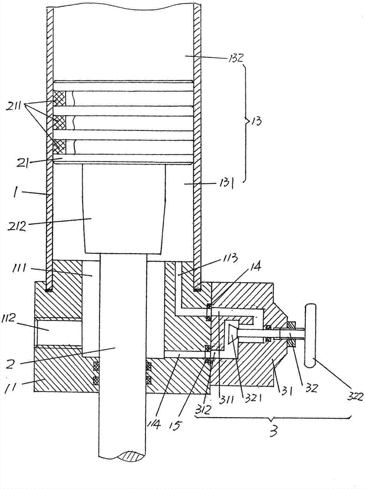
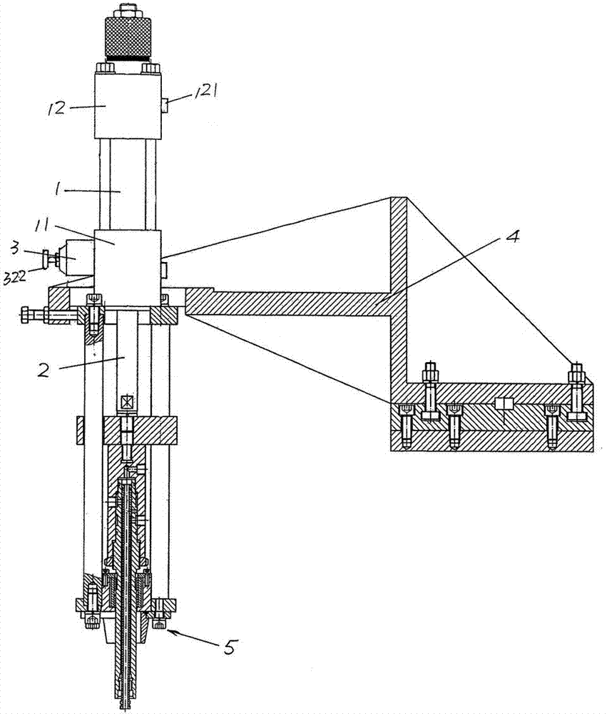
[0019] Please see figure 1 with figure 2 , given the cylinder head 11 and tailstock 12 ( figure 2 Shown) the oil cylinder body 1, the oil cylinder body 1 is fixed between the oil cylinder head 11 and the tailstock 12 by a set of fixing rods. The cylinder chamber of the oil cylinder block 1 is formed as an oil chamber 13, and the oil cylinder column 2 that moves up and down (taking the position shown in the figure as an example) is arranged in the oil chamber 13 .

[0020] The aforementioned cylinder head 11 forms a cylinder head buffer oil chamber 111, and an oil cylinder head inlet and outlet hole 112 is opened on the side of the cylinder head 11, and the oil cylinder head inlet and outlet hole 112 is provided with an oil inlet and outlet joint (not shown in the figure) , the oil inlet and outlet joints are connected to the oil pump or similar hydraulic oil devices through pipelines. An oil cylinder column piston head 21 with a diameter larger than that of the oil...


PUM


Abstract

The invention relates to a buffer oil cylinder for plastic product forming machinery and belongs to the technical field of power sources of plastic product forming machinery. The buffer oil cylinder comprises an oil cylinder body and an oil cylinder column, wherein the oil cylinder body with an oil cylinder head at one end and a tail seat at the other end is provided with an oil cylinder head buffer oil cavity and an oil inlet and outlet hole, and the oil cylinder column is arranged in an oil cavity of the oil cylinder body. The tail seat is provided with a tail seat oil inlet and outlet hole, an oil cylinder column piston head is additionally arranged at one end of the oil cylinder column towards the tail seat, and a piston head sealing ring is arranged on the oil cylinder column piston head. The buffer oil cylinder for plastic product forming machinery is characterized in that a buffer column is formed on the surface of the oil cylinder piston head, the oil cylinder head is provided with an oil outlet hole and an oil return hole , a pressure oil flow adjusting mechanism is arranged on the outer wall of the oil cylinder head and communicated with the oil outlet hole and the oil return hole at the same time and controls flow of pressure oil entering the oil return hole from the oil outlet hole. Accordingly, the oil cylinder head is protected from being collided by the oil cylinder column piston head, no damage to the oil cylinder body is caused, and the buffer oil cylinder is simple in structure, easy to manufacture and mount.

Description

technical field [0001] The invention belongs to the technical field of power sources of plastic product molding machines, and in particular relates to a buffer oil cylinder for plastic product molding machines. Background technique [0002] Oil cylinders for plastic product molding machinery can be found in the following patents, which are not limited to, ZL01244534.7 (mold shifting mechanism), ZL01244535.5 (opening and closing mold cylinder with improved structure), ZL200420027711.X (plastic hollow molding machine clamping and locking mechanism for hollow plastic molding machine), ZL200920035666.5 (mold clamping and locking mechanism for hollow plastic molding machine), ZL201020157649.1 (mold opening and closing mechanism), ZL201020157674.X (magnetic clamping cylinder for hollow plastic product molding machine) And ZL201120312034.6 (elbow-hugging mold opening and closing mechanism) and so on. And plastic product molding machines such as injection molding machines and blow ...

Claims


Application Information

Patent Timeline
Patent Type & Authority Applications(China)
IPC IPC(8): F15B15/22
Inventor 吴国春刘俊
Owner SUZHOU TONGDA MACHINERY
Learn More