Flexible flat heat pipe

A flat heat pipe, flexible technology, applied in the direction of indirect heat exchangers, lighting and heating equipment, etc., can solve the problems of irregular heat dissipation surface, low thermal conductivity of heat pipe, poor sealing, etc., to achieve light and easy to manufacture, High thermal conductivity, good sealing effect

Inactive Publication Date: 2014-05-07
NANJING UNIV OF AERONAUTICS & ASTRONAUTICS
View PDF5 Cites 0 Cited by
  • Summary
  • Abstract
  • Description
  • Claims
  • Application Information

AI Technical Summary

Problems solved by technology

[0003] In order to solve the problems of low thermal conductivity, poor sealing and inapplicability to irregular heat dissipation surfaces of existing heat pipes, the present invention provides a flexible flat heat pipe. Thermal conductivity, and good sealing, so it can be used on some special components such as high heat flux density, small area electronic components, etc.

Method used


Image

  • Flexible flat heat pipe
  • Flexible flat heat pipe
  • Flexible flat heat pipe

Examples


Embodiment Construction

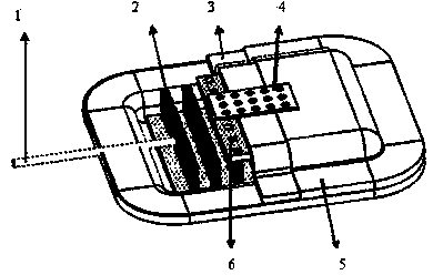
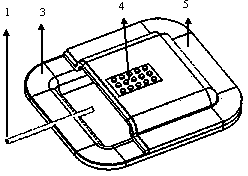
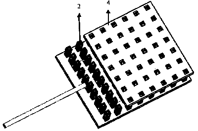
[0011] figure 1 , the working fluid enters the capillary structure through the liquid-filled tube 1.

[0012] The working medium used is water.

[0013] The entire sintered interior is covered with a layer of silicon rubber cover 5, and the cover is bonded through silicon rubber.

[0014] The casing 3 is composed of upper and lower parts, and the edge adopts a curling sealing structure, which is more conducive to the overall sealing of the heat pipe.

[0015] In the center of the upper and lower surfaces of the silicone rubber cover, there are areas accounting for about 30% of the surface area of ​​the entire cover. Copper is electroplated in these areas, and the electroplated copper is in contact with the shell, which is beneficial to the heat conduction of the flat heat pipe.


PUM


Abstract

The invention discloses a flexible flat heat pipe, and belongs to the technical field of heat transfer. The heat pipe comprises a liquid charging pipe (1), a flow guide column (2), a shell (3), a heat transfer area (4), a silicon rubber cover (5) and a sintering copper net (6), wherein the flow guide column and the sintering copper net form a capillary core structure of the flat heat pipe. The heat pipe not only has high heat conductivity and can be bent, but also has great tightness and thus has strong surface adaptability.

Description

Technical field [0001] The invention relates to a flexible flat heat pipe, which belongs to the technical field of heat transfer. Background technique [0002] With the development of electronic technology, small flat heat pipe is an emerging technology that has gradually been paid attention to. Its purpose is mainly to provide better heat dissipation for various electronic components with high heat flux density and small area. With the rapid development of science and technology, the heat output per unit of electronic components is increasing. Due to the limitation of its own thermal conductivity, the traditional thermal diffusion plate can only distribute the heat flow evenly to a certain extent; in addition, the existing flat plate Heat pipes cannot be bent, and are not suitable for devices with curved surfaces. Contents of the invention [0003] In order to solve the problems of low thermal conductivity, poor sealing and inapplicability to irregular heat dissipation s...

Claims


Application Information

Patent Timeline
Patent Type & Authority Patents(China)
IPC IPC(8): F28D15/04
CPCF28D15/0241
Inventor 史波张昊王义彪单英杰
Owner NANJING UNIV OF AERONAUTICS & ASTRONAUTICS
Why Eureka
Try Eureka