Pneumatic optical wavefront ultra-high frequency measurement system and method

An aero-optics and measurement system technology, applied in the aerospace field, can solve problems such as not being strictly correct, and achieve the effect of reducing interval time, shortening time interval, and realizing ultra-high frequency measurement

Active Publication Date: 2013-01-02
NAT UNIV OF DEFENSE TECH
View PDF4 Cites 12 Cited by
  • Summary
  • Abstract
  • Description
  • Claims
  • Application Information

AI Technical Summary

Problems solved by technology

However, in the actual flow field, the convective velocity is unsteady, and the flow field structure also develops and changes, so the assumption of frozen flow is not strictly correct

Method used


Image

  • Pneumatic optical wavefront ultra-high frequency measurement system and method
  • Pneumatic optical wavefront ultra-high frequency measurement system and method

Examples


Embodiment Construction

[0019] The embodiments of the present invention will be described in detail below with reference to the accompanying drawings, but the present invention can be implemented in many different ways defined and covered by the claims.

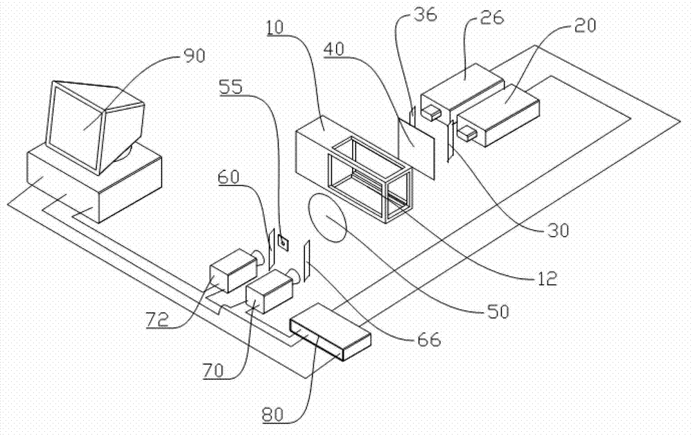
[0020] see figure 1 , the aero-optical wavefront UHF measurement system of the preferred embodiment of the present invention is used for UHF measurement of the aero-optic wavefront distortion of the laser beam passing through the wind tunnel experiment cabin 10 . The wind tunnel experiment cabin 10 includes an optical window 12 , so that the background image light illuminated by the laser beam passes through the optical window 12 of the wind tunnel experiment cabin 10 . During the aero-optic wavefront test, a supersonic flow field is generated in the wind tunnel experiment cabin 10 .

[0021] The aero-optic wavefront measurement system includes a first dual-cavity laser 20 and a second dual-cavity laser 26 arranged side by side, a first half mirror...


PUM


Abstract

The invention provides a pneumatic optical wavefront ultra-high frequency measurement system. The pneumatic optical wavefront ultra-high frequency measurement system comprises a first dual-cavity laser device and a second dual-cavity laser device, a first semi-transparent mirror opposite to a light outlet of the first dual-cavity laser device, a first reflector opposite to the light outlet of the second dual-cavity laser device, a first CCD (charge coupled device) camera and a second CCD camera, a synchronous controller, a computer system, a second semi-transparent mirror, a second reflector, a background image, a convex lens and a pore, wherein the first CCD camera and the second CCD camera are arranged in parallel; the computer system is connected to the first CCD camera, the second CCD camera and the synchronous controller; the second semi-transparent mirror is opposite to the lens of the second CCD camera; the second reflector is opposite to the lens of the first CCD camera; the backlight image, the convex lens and the pore are respectively arranged at two opposite sides of a wind tunnel experiment module; the backlight image and the second dual-cavity laser device are arranged at the same side; and the first CCD camera, the second CCD camera, the first dual-cavity laser device and the second dual-cavity laser device are connected to the synchronous controller respectively. The invention also relates to a measurement method. According to the method, the shot background image is subjected to analysis calculation by the computer, so that ultra-high frequency measurement of whole-field pneumatic optical wavefront distortion is achieved.

Description

technical field [0001] The invention relates to the field of aerospace, in particular to an aero-optical wavefront ultra-high frequency measurement system used in the fields of supersonic imaging guidance, aerial photography, airborne telescope and the like. Furthermore, the invention also relates to a method comprising the above-mentioned measuring system. Background technique [0002] The aero-optical wavefront measurement technique can be used to study the aero-optical effects encountered in the fields of supersonic imaging guidance, aerial photography and airborne telescopes. There are many existing measurement methods, such as: interferometry, small aperture beam technology and Malley probe measurement method. The commonly used Malley probe measurement method uses a position sensor to measure the deflection of the beam at a very high frequency, which can only measure a single point wavefront and cannot perform full-field measurement. The Malley probe measurement metho...

Claims


Application Information

Patent Timeline
Patent Type & Authority Applications(China)
IPC IPC(8): G01J9/00G01M9/06
Inventor 易仕和田立丰陈植何霖赵玉新周勇为
Owner NAT UNIV OF DEFENSE TECH
Why Eureka
Try Eureka