

Online leakage detection method and device thereof for heat treatment furnace radiant tube
A technology of heat treatment furnace and radiant tube, which is applied in the direction of measuring the acceleration and deceleration rate of fluid, using liquid/vacuum degree for liquid tightness measurement, etc. Improved accuracy and reliability, shorter test cycles, and less labor-intensive effects
- Summary
- Abstract
- Description
- Claims
- Application Information
AI Technical Summary
Problems solved by technology
Method used
Image

Examples
Embodiment 1
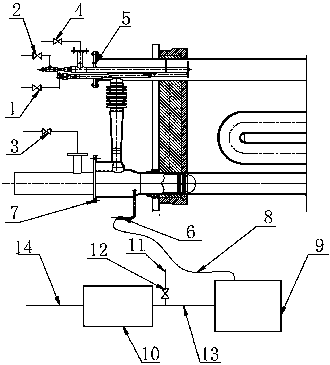
[0026] Such as figure 1 A heat treatment furnace radiant tube online leak detection device shown includes a gas flowmeter 9 and a vacuum sampling pump 10, the gas inlet of the gas flowmeter 9 is connected to one end of the gas sampling pipe 8, and the other end of the gas sampling pipe 8 is used In connection with the sampling head 6 of the radiant tube burner, the exhaust port of the gas flow meter 9 is connected with one end of the gas suction pipe 13 , and the other end of the gas suction pipe 13 is connected with the intake end of the vacuum sampling pump 10 . The gas suction pipe 13 is provided with a protection branch pipe 11 communicating with the atmosphere, the protection branch pipe 11 is provided with an on-off valve 12 , and the gas outlet end of the vacuum sampling pump 10 is provided with a waste gas outlet pipe 14 .
[0027] When the above device performs on-line leak detection of the radiant tube of the heat treatment furnace, the following steps are included: ...
Embodiment 2
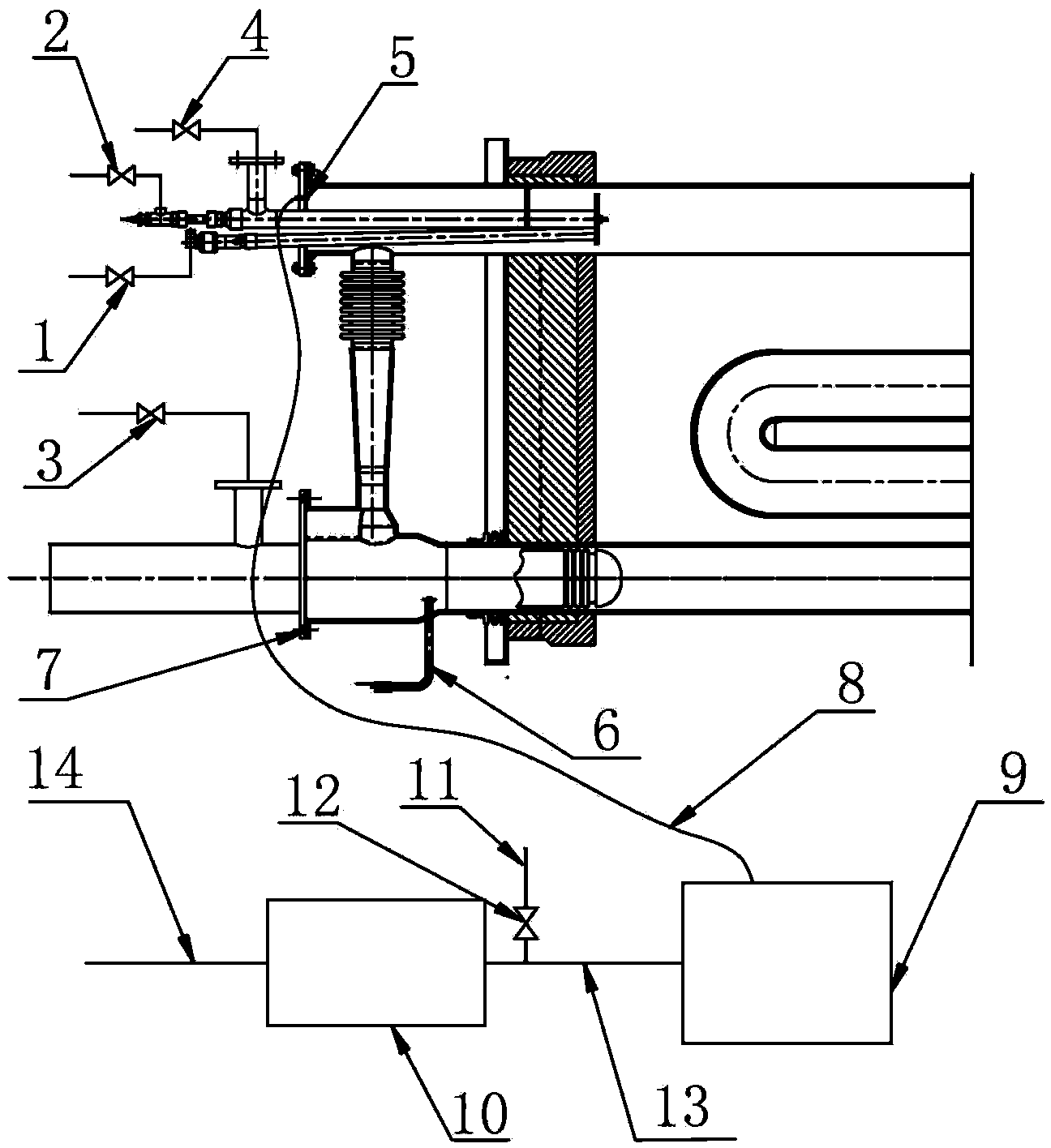
[0032] Such as figure 2 Another heat treatment furnace radiant tube online leak detection device shown includes a gas flowmeter 9 and a vacuum sampling pump 10. The gas inlet of the gas flowmeter 9 is connected to one end of the gas sampling pipe 8, and the other end of the gas sampling pipe 8 is It is used to connect the pressure measuring nozzle 5 on the end face of the radiant tube burner. The exhaust port of the gas flowmeter 9 is connected to one end of the gas suction pipe 13 , and the other end of the gas suction pipe 13 is connected to the intake end of the vacuum sampling pump 10 . The gas suction pipe 13 is provided with a protection branch pipe 11 communicating with the atmosphere, the protection branch pipe 11 is provided with an on-off valve 12 , and the gas outlet end of the vacuum sampling pump 10 is provided with a waste gas outlet pipe 14 . The gas sampling pipe 8, the gas suction pipe 13 and the waste gas outlet pipe 14 can adopt flexible pipes or hard pipes...
PUM
 Abstract
Description
Claims
Application Information