Weighting sparse-driven self-focusing SAR (Synthetic Aperture Radar) imaging method

An imaging method and self-focusing technology, applied in the direction of radio wave reflection/re-radiation, using re-radiation, measuring devices, etc., can solve the problems of echo data phase error, model error, image defocus, etc.

Inactive Publication Date: 2013-01-02
UNIV OF ELECTRONICS SCI & TECH OF CHINA
View PDF3 Cites 14 Cited by
  • Summary
  • Abstract
  • Description
  • Claims
  • Application Information

AI Technical Summary

Problems solved by technology

Synthetic aperture radar (SAR) imaging depends on the observation model of the observation process. Due to the model error introduced by the motion error, there will be a certain phase error in the echo data, which will defocus the reconstructed image.
After the image is defocused, it will seriously affect the quality of reconstruction, and there will be false targets and high side lobes

Method used


Image

  • Weighting sparse-driven self-focusing SAR (Synthetic Aperture Radar) imaging method
  • Weighting sparse-driven self-focusing SAR (Synthetic Aperture Radar) imaging method
  • Weighting sparse-driven self-focusing SAR (Synthetic Aperture Radar) imaging method

Examples


Embodiment Construction

[0108] The present invention mainly uses simulation experiments to verify the feasibility of the system model, and all steps and conclusions are verified correctly on MATLAB 7.9.0. The specific implementation steps are as follows:

[0109] Step 1. Radar system parameters and parameter setting of weighted sparse drive autofocus method

[0110] The system parameters used in the specific implementation of this step are detailed in Figure 5 , The parameters used in the weighted sparse drive self-focusing method are detailed in Figure 4 .

[0111] Step 2: Construct a linear observation model of the radar echo signal and the scattering coefficient of the observation scene

[0112] It includes the following steps:

[0113] Step 2.1:

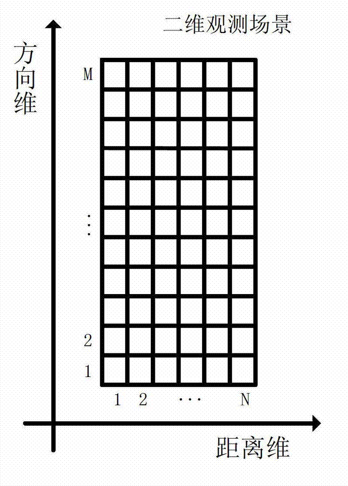
[0114] Divide the observation range of the distance dimension of the two-dimensional observation scene [-22.5 meters, 22.5 meters] into 61 distance dimension units at equal intervals with a distance dimension resolution of 0.75 meters, and record them as dista...


PUM


Abstract

The invention discloses a weighting sparse-driven self-focusing SAR (Synthetic Aperture Radar) imaging method. The method comprises the steps as follows: establishing a linear observing model of echo data and an observing scene to construct the optimized target function; adopting the weighted L1 norm; and then carrying out an L1 norm approximating method to approximate the L1 norm in the target function; iterating and solving the optimized target function; and estimating the phase error of the linear observing model, and modifying the linear observing model to obtain a more accurate observing model, thus achieving the focusing of the synthetic aperture radar (SAR) image. Compared with the synthetic aperture radar (SAR) image reconstructed via a traditional focusing method (such as PGA (Programmable Gain Amplifier) and a sparse-driven auto-focusing (SDA), the synthetic aperture radar image obtained via the method provided by the invention is lower in sidelobe, and has a better effect on focusing.

Description

Technical field [0001] The invention belongs to the field of radar imaging technology, and particularly relates to the field of synthetic aperture radar (SAR) imaging technology. Background technique [0002] Synthetic Aperture Radar (SAR) is a high-resolution microwave imaging system that relies on the relative motion between the radar and the target to form a synthetic array to obtain horizontal high resolution, and uses large bandwidth signals to achieve vertical high resolution. Synthetic Aperture Radar (SAR) imaging relies on the observation model of the observation process, and the model error introduced by the motion error will cause a certain phase error in the echo data, and then defocus the reconstructed image. After the image is defocused, it will seriously affect the quality of reconstruction, and false targets and high sidelobes will appear. In order to solve the problem of image defocus, a self-focusing method was created. One of the more well-known autofocus meth...

Claims


Application Information

Patent Timeline
Patent Type & Authority Applications(China)
IPC IPC(8): G01S13/90
Inventor 张晓玲彭文杰
Owner UNIV OF ELECTRONICS SCI & TECH OF CHINA
Why Eureka
Try Eureka