
Method for manufacturing broad-spectrum strong-focusing Fresnel lens

A technology of a Fresnel lens and a manufacturing method, applied in the optical field, can solve the problems of poor concentrating sunlight effect, difficulty in obtaining high conversion efficiency, and the like

Active Publication Date: 2013-01-02
HARBIN INST OF TECH
View PDF3 Cites 6 Cited by
  • Summary
  • Abstract
  • Description
  • Claims
  • Application Information

AI Technical Summary

Problems solved by technology

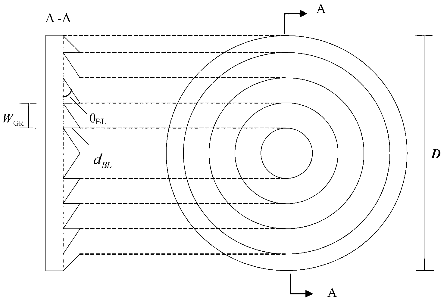
[0004] The purpose of the present invention is to solve the problem that the Fresnel lens of the traditional concentrating system imaging has poor sunlight converging effect and is difficult to obtain a higher conversion efficiency, and provides a method for manufacturing a wide-spectrum strong focusing Fresnel lens

Method used


Image

  • Method for manufacturing broad-spectrum strong-focusing Fresnel lens
  • Method for manufacturing broad-spectrum strong-focusing Fresnel lens
  • Method for manufacturing broad-spectrum strong-focusing Fresnel lens

Examples


specific Embodiment approach 1

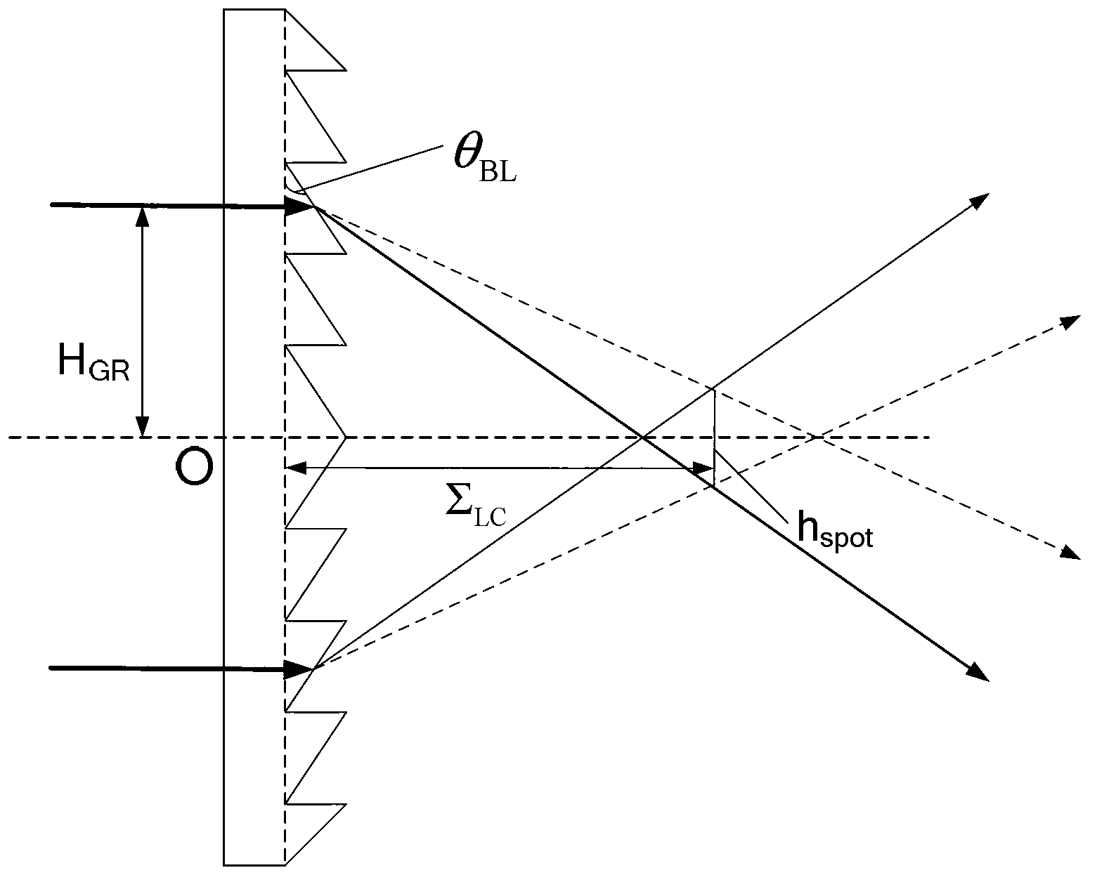
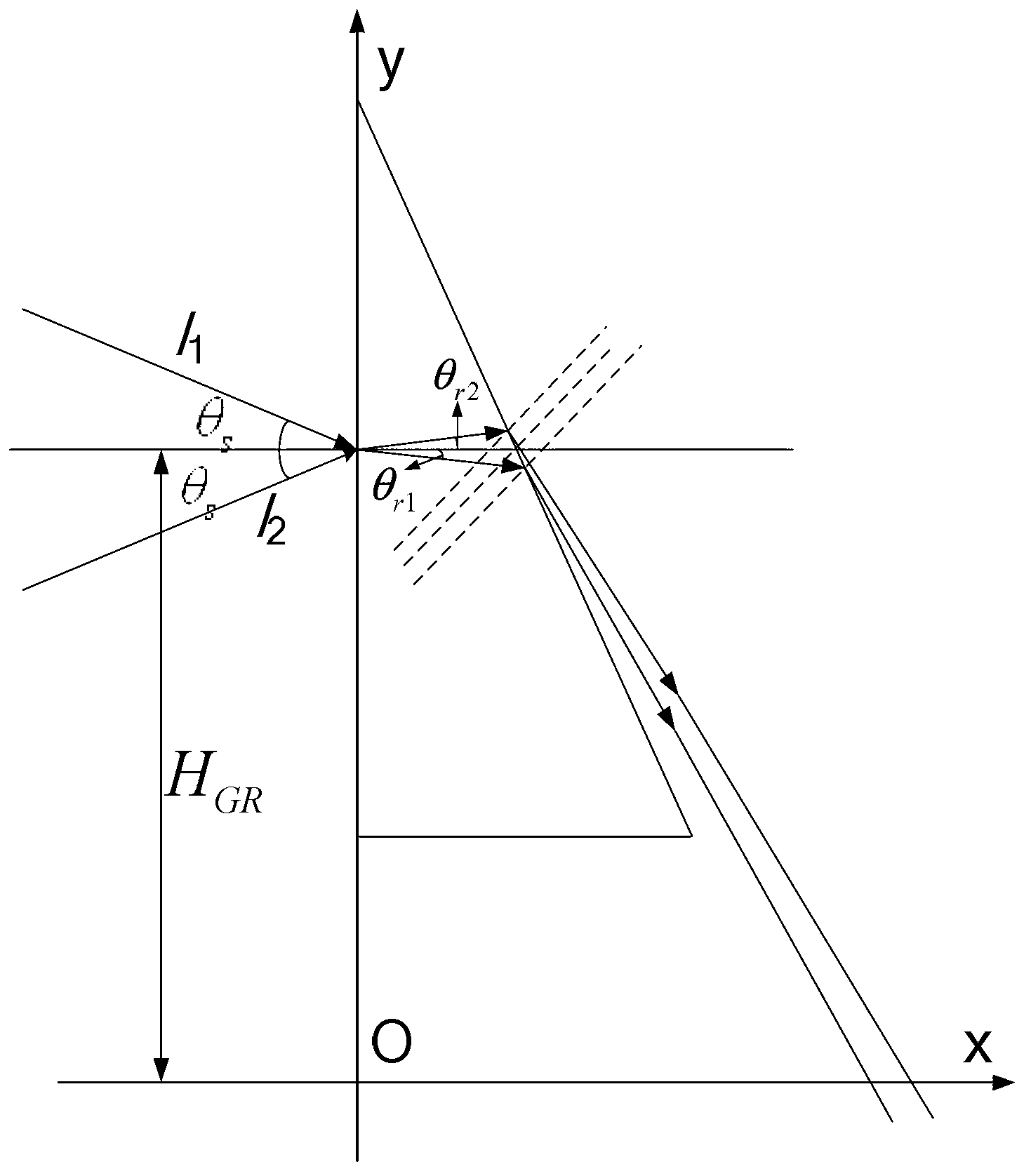
[0032] Specific implementation mode one: the following combination Figure 1 to Figure 3 Describe this embodiment mode, the manufacturing method of a kind of wide-spectrum strong focusing Fresnel lens described in this embodiment mode, the realization process of this method is:

[0033] Step 1, setting the iterative relationship between the inclination angle of the ring of the Fresnel lens to be made and the distance of the ring from the center of the lens circle is:

[0034] H GR = H GR - 1 + d BL / 2 tan ( θ BL ) + d BL / ...

specific Embodiment approach 2

[0050] Specific implementation mode two: the following combination Figure 1 to Figure 3 Describe this embodiment, this embodiment is to obtain θ for Embodiment 1 BL with H GR Further description of the iterative relational formula of the present embodiment, step 3 described in this embodiment, uses the estimation and correction algorithm to solve formula (3) and formula (5) iteratively to obtain θ BL with H GR The method is: according to W GR 、H GR with theta BL Direct relationship:

[0051] tan ( sin - 1 [ n R sin θ BL ] - θ BL ) = 2 H GR Σ LC ...

specific Embodiment approach 3

[0054] Specific implementation mode three: the following combination Figure 1 to Figure 3 Describe this embodiment. This embodiment is a further description of the estimation and correction algorithm used in Embodiments 1 and 2. The estimation and correction algorithm described in this embodiment is used to solve formula (3) and formula (5). The inclination angle θ of each ring BL with ring height H GR The predictive and corrective formulas of the predictive correction algorithm are:

[0055] y n + 1 * = y n - q + h Σ ...


PUM


Abstract

The invention provides a method for manufacturing a broad-spectrum strong-focusing Fresnel lens, belonging to the optics field. The method is used to solve the problems that a Fresnel lens imaging through a traditional concentration system has a poor effect of converging sunlight and is difficult to obtain higher conversion efficiency. A realization process of the method comprises the following steps: firstly, obtaining a iteration relation between dip angle ThetaBL of a ring zonal gear of a Fresnel lens and ring height HGR of the Fresnel lens by computation after a divergence angle Thetas of incident sunlight is introduced; adopting a prediction-correction algorithm to obtain an dip angle ThetaBL and ring height HGR of each ring, and using a Monte Carlo radiosity algorithm to obtain a power density Psi of the sunlight received by a fixed area in a focal plane; obtaining a power density limit value Psilim based on an imaging concentration principle; and calculating a spectrum range of a to-be-manufactured Fresnel lens : absolute value of (Psilim-Psi) is less than or equal to Epsilon, and manufacturing a die according to final parameters of the Fresnel lens obtained by simulation so as to obtain a lens entity. The methodprovided byf the invention is used for manufacturing the broad-spectrum strong-focusing Fresnel lens.

Description

technical field [0001] The invention relates to a design method for a Fresnel concentrator aiming at strong focusing of solar spectrum, which belongs to the field of optics. Background technique [0002] With the rapid depletion of fossil fuels and the need for sustainable development, human beings urgently need to find a clean energy source. However, due to technical bottlenecks, the annual actual utilization of solar energy, which is the first choice for all clean energy, only accounts for 0.1% of the world's total power generation, which is equivalent to the solar radiation energy (4.3×10²⁰J) received by the ground within one hour. It can be seen that the expansion space for solar energy utilization is very huge. [0003] Since the content of magnesium element in the earth's crust occupies the eighth place, the concentration of MgO in the seawater on the earth's surface is very rich at 1.3g / l, and the element content is the second place, so it can be converted into laser...

Claims


Application Information

Patent Timeline
Patent Type & Authority Applications(China)
IPC IPC(8): G02B3/08G02B19/00G02B27/00
Inventor 芦宇申作春鲁建业崔峥刘永强
Owner HARBIN INST OF TECH
Learn More