Novel floater type liquid level automatic control device

A liquid level automatic control, float type technology, applied in liquid level control, non-electric variable control, control/regulation system and other directions, can solve the problems of unstable force transmission, easy falling off, force transmission failure of gears, etc., and achieve extended use. Long life, good control effect and good force transmission effect

Inactive Publication Date: 2013-01-02
连云港市荣泰碳化硅有限公司
View PDF5 Cites 9 Cited by
  • Summary
  • Abstract
  • Description
  • Claims
  • Application Information

AI Technical Summary

Problems solved by technology

Although the device is simple in structure and small in size and solves some technical problems, it also has defects: one is that the hollow float is generally made of plastic with air inside, and its specific gravity is smaller than that of water. Although the buoyancy is very good, it can control the water surface The gravity of the float is obviously insufficient when descending, so the two-way force transmission of the force transmission mechanism is inconsistent and the force transmission of the gear is unstable. A certain arc, if the two-way force transmission is inconsistent and the gear transmission force is unstable, it will easily cause the operation of the lever to fail; the third is that the device does not consider the control of the liquid level other than the water outlet, so the applicatio

Method used


Image

  • Novel floater type liquid level automatic control device
  • Novel floater type liquid level automatic control device
  • Novel floater type liquid level automatic control device

Examples


Embodiment Construction

[0018] Below in conjunction with accompanying drawing, the present invention is described in further detail:

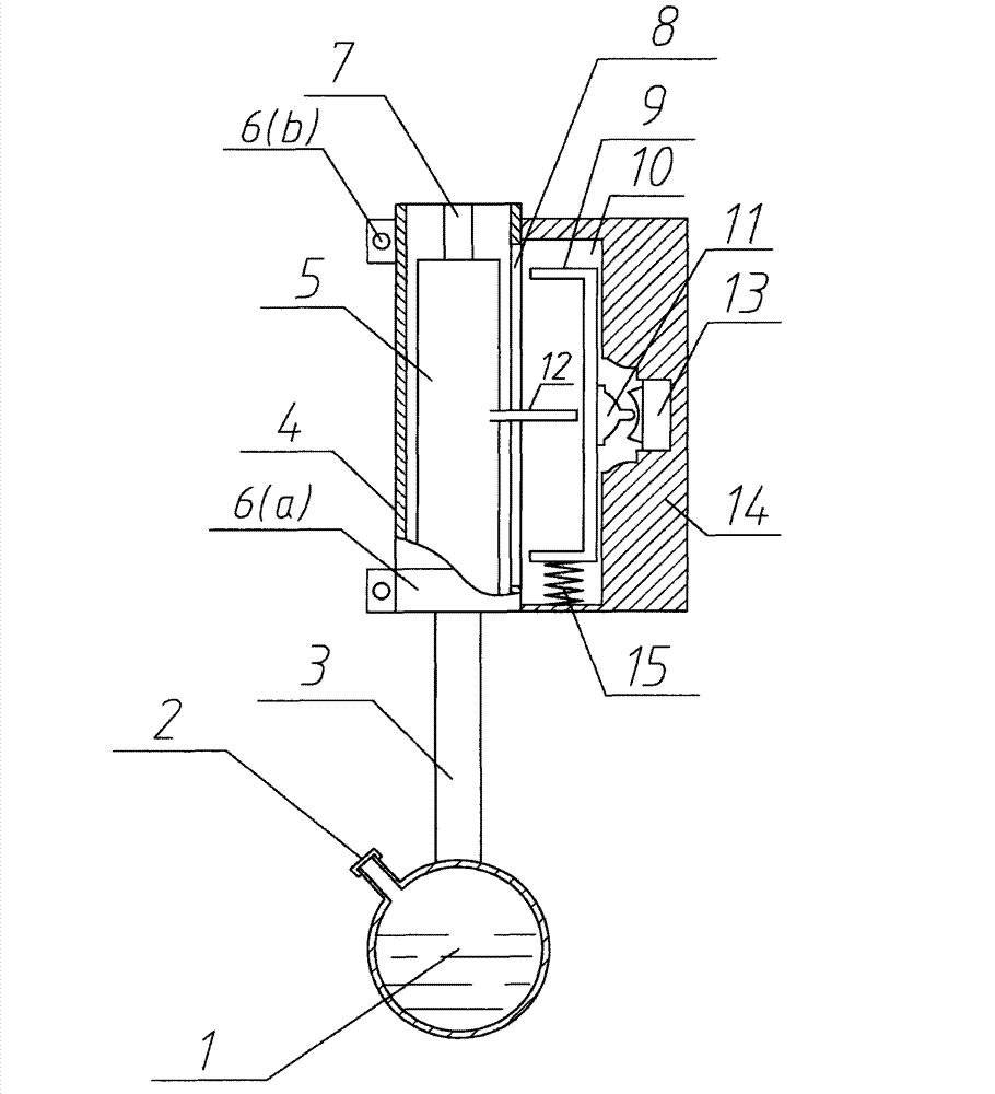
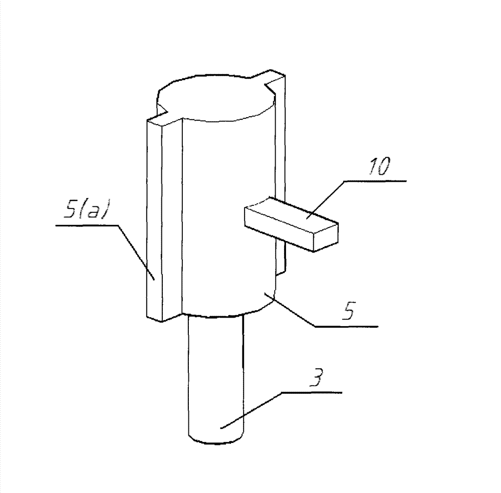
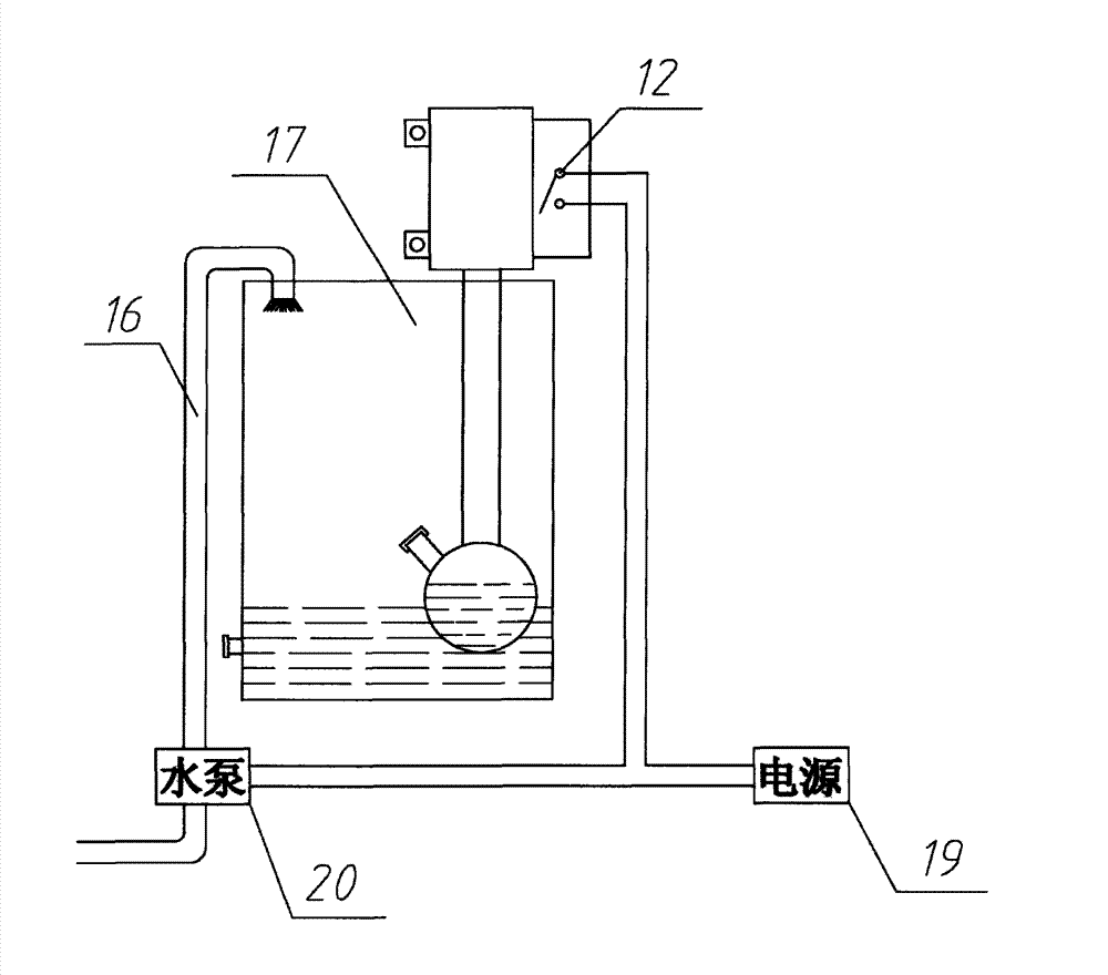
[0019] see figure 1 , 2 , 3, a new float type liquid level automatic control device, including float 1,, slide 4, slide rod 5, toggle lever 9, toggle lever cavity 10, power switch 13 and some auxiliary devices. It is characterized in that one end of the long arm 3 is connected with a float 1, and one end is connected with a slide bar 5; the slide bar 5 is provided with a slide bar 5 (a); ) corresponding to the slideway 7, so that the slide bar 5 can slide vertically in the slide tube 4; the slide bar 5 is provided with a lever 12 for toggling the toggle lever 9; the toggle lever 9 is provided with a vertical shift block 11 is used for toggling power switch 13; This power switch 13 is connected with the electric device that feeds water tank 17 water supply.

[0020] see figure 1 One side of the slider 4 of the present invention is provided with a lever slide hole 8...


PUM


Abstract

Disclosed is a novel floater type liquid level automatic control device which comprises a floater, a long arm, a sliding barrel, a sliding rod, a shift rod, a shift rod cavity and a power switch. The novel floater type liquid level automatic control device is characterized in that one end of the long arm is connected with the floater, and the other end of the long arm is connected with the sliding rod; a slide way rod is arranged on the sliding rod, and a slide way corresponding to the slide way rod is arranged in the sliding barrel so that the sliding rod can vertically slide in the sliding barrel; a prodding rod which is used for prodding the shift rod is arranged on the sliding rod; a vertical shift block is arranged on the shift rod and used for shifting the power switch; and the power switch is connected with an electric device which supplies water for a water tank. A prodding rod sliding hole is opened on one side of the sliding barrel so that the prodding rod can perform upward and downward prodding along the prodding rod sliding hole during operation of the device to drive the shift rod to move upwards and downwards; and the vertical shift block is arranged on the shift rod and is capable of driving the power switch to be opened and closed to automatically control liquids. The novel floater type liquid level automatic control device has the advantages of being simple in structure, cheap, good in power transmission effects and control effects and capable of being widely used for storing water and controlling the liquids in rural areas, cities and the like.

Description

technical field [0001] The invention relates to a liquid level control device, in particular to a float type liquid level automatic control device. Background technique [0002] Since the beginning of the 21st century, the rapid development of the world economy has caused human beings to overdraw the earth's resources in advance. Water resources have become the most scarce natural resources today. Water conservation and rational use of water are now the top priority for human survival. [0003] Existing water storage facilities are generally equipped with water level control systems, usually manual and automatic. In the automatic water level control system, a simple mechanical device such as a water toilet tank, which manually lowers the water level and then makes the float drive the valve piston to inject water; it is not only easy to damage during use, but also not suitable for large water storage facilities The water level is automatically controlled. Complicated water ...

Claims


Application Information

Patent Timeline
IPC IPC(8): G05D9/02G05D9/12
Inventor 王龙孟正萍
Owner 连云港市荣泰碳化硅有限公司
Why Eureka
Try Eureka