
Artificial composite material and artificial composite material antenna

An artificial composite material and antenna technology, applied in the electromagnetic field, can solve the problems of poor lens performance, large diffraction and reflection, etc.

Active Publication Date: 2013-01-02
KUANG CHI INST OF ADVANCED TECH +1
View PDF4 Cites 0 Cited by
  • Summary
  • Abstract
  • Description
  • Claims
  • Application Information

AI Technical Summary

Problems solved by technology

[0003] The technical problem to be solved by the present invention is to provide a high-performance artificial composite material and artificial composite material antenna for the defects of the prior art that the above-mentioned refraction, diffraction and reflection are relatively large, and the lens performance is poor.

Method used


Image

  • Artificial composite material and artificial composite material antenna
  • Artificial composite material and artificial composite material antenna
  • Artificial composite material and artificial composite material antenna

Examples


Embodiment Construction

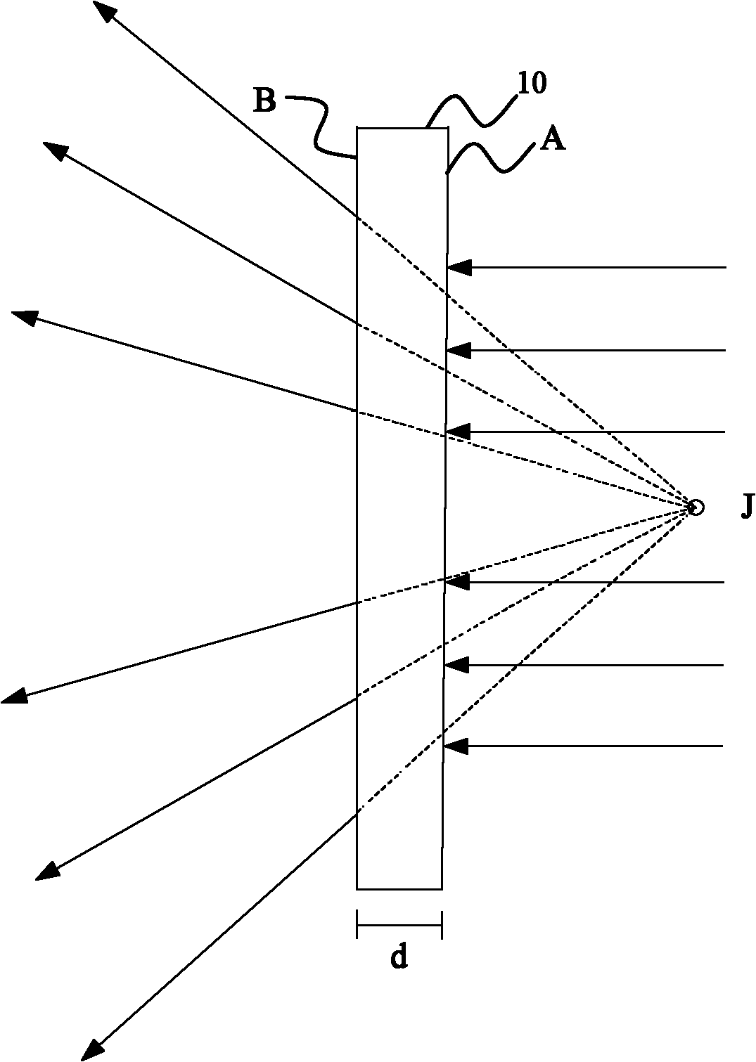
[0039] figure 1 It is a schematic diagram of the divergence effect of the artificial composite material 10 on electromagnetic waves according to an embodiment of the present invention. The artificial composite material 10 is relatively arranged in the electromagnetic wave propagation direction of the radiation source. The plane electromagnetic wave is incident on the first surface A of the artificial composite material and emerges from the second surface B opposite to the first surface A in the form of a spherical wave. The emitted electromagnetic waves reversely extend and intersect at the virtual focal point J of the artificial composite material.

[0040] As common knowledge, we know that the refractive index of electromagnetic waves is related to In direct proportion, when a beam of electromagnetic wave propagates from one medium to another medium, the electromagnetic wave will be refracted. When the refractive index distribution inside the material is non-uniform, the e...


PUM


Abstract

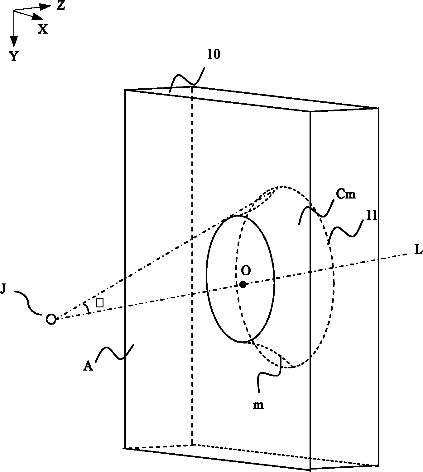
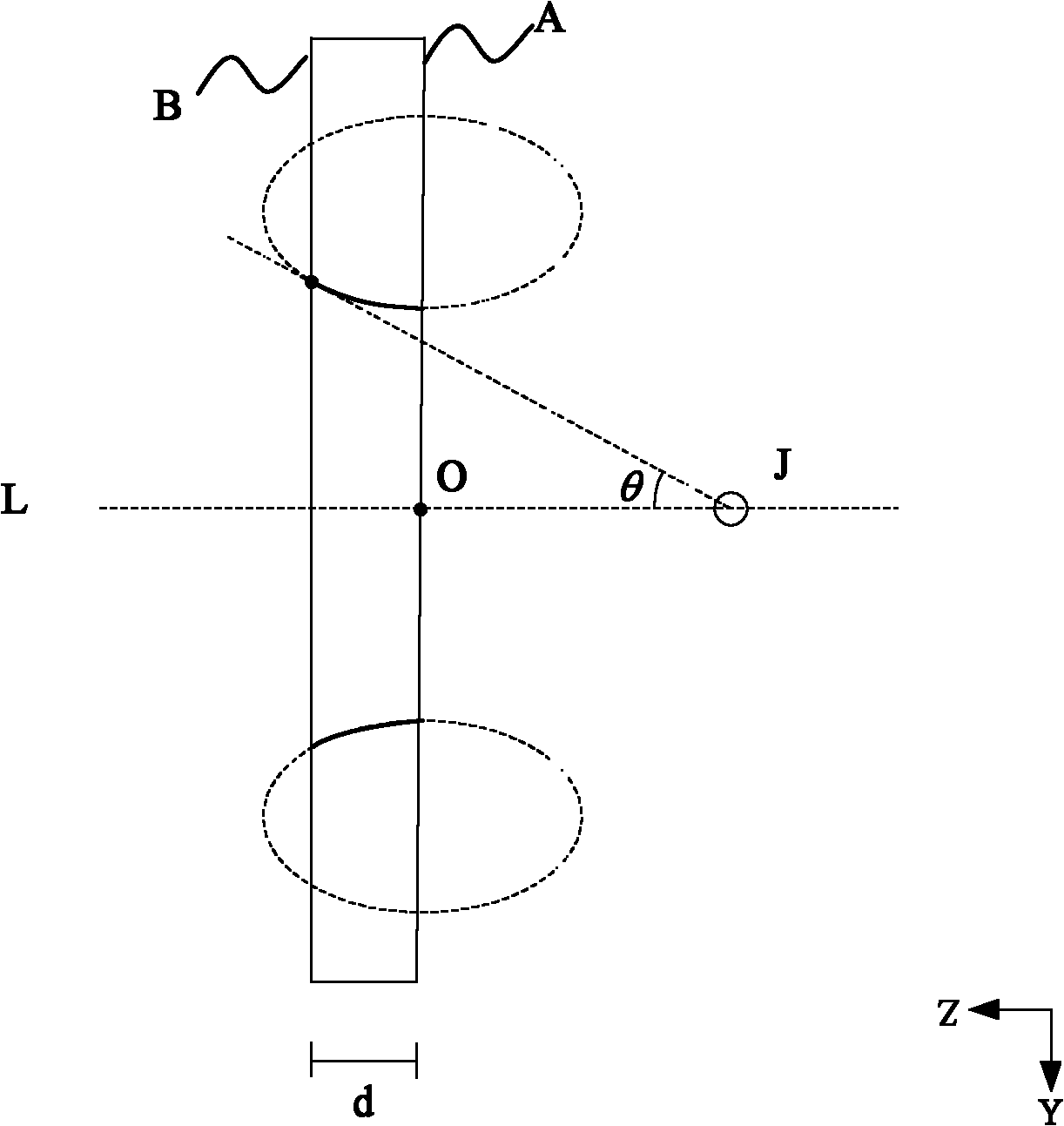
The invention relates to an artificial composite material and an artificial composite material antenna. The artificial composite material is oppositely arranged in the electromagnetic wave propagation direction of a radiation source, wherein the included angle between the line connecting the radiation source and a point on a first surface of the artificial composite material and a straight line vertical to the artificial composite material is supposed to be theta; the included angle theta only corresponds to a curved surface in the artificial composite material; the refractive index of each part on the curved surface is the same; the generatrix of the curved surface is an elliptic arc; the refractive index of the artificial composite material gradually decreases along with increase of the included angle theta; and the electromagnetic waves are jetted from the top surface of each torus in parallel after passing through the artificial composite material. The artificial composite material and the artificial composite material antenna have the following beneficial effects that by designing the jump of the refractive index of the artificial composite material into a curved surface, the refraction, diffraction and reflection effects in the jump positions are greatly reduced and the problems caused by mutual interference are reduced, so that the artificial composite material and the artificial composite material antenna have more excellent performances.

Description

technical field [0001] The invention relates to the electromagnetic field, and more specifically, relates to an artificial composite material and an artificial composite material antenna. Background technique [0002] In conventional optical devices, a lens enables a plane wave to be refracted by the lens into a spherical wave that appears to radiate from a point source of light at the virtual focus of the lens. At present, the divergence of the lens is realized by the refraction of the spherical shape of the lens. In the process of implementing the present invention, the inventor found that the lens antenna has at least the following technical problems: the lens is large and heavy, which is not conducive to the use of miniaturization; the lens has a great dependence on the shape, and it needs to be more precise to realize the orientation of the antenna Propagation; electromagnetic wave reflection interference and loss are more serious, and electromagnetic energy is reduced...

Claims


Application Information

Patent Timeline
IPC IPC(8): H01Q15/02H01Q19/06
Inventor 刘若鹏季春霖岳玉涛
Owner KUANG CHI INST OF ADVANCED TECH
Learn More