
Automatic assembling machine for micro motor rotor

An automatic assembly machine and micro-motor technology, applied in the manufacture of stator/rotor bodies, etc., can solve the problems of standardization, mechanization, large-scale production, unstable product quality, and low product qualification rate of micro-motors, and meet the requirements of large-scale Large-scale standardized production, high assembly efficiency, and high degree of automation

Active Publication Date: 2013-01-02
DONGGUAN YI CHENG AUTOMATIC EQUIP
View PDF5 Cites 40 Cited by
  • Summary
  • Abstract
  • Description
  • Claims
  • Application Information

AI Technical Summary

Problems solved by technology

[0002] The micro motor rotor is composed of the rotor shaft and more than one magnetic ring. The traditional assembled micro motor rotor is manually assembled, which has the disadvantages of low assembly efficiency, unstable product quality, low product qualification rate, and high labor cost. Meet the demand for standardization, mechanization and mass production of micro motors

Method used


Image

  • Automatic assembling machine for micro motor rotor
  • Automatic assembling machine for micro motor rotor
  • Automatic assembling machine for micro motor rotor

Examples


Embodiment Construction

[0027] The following is the best example of the micro motor rotor automatic assembly machine of the present invention, which does not limit the protection scope of the present invention.

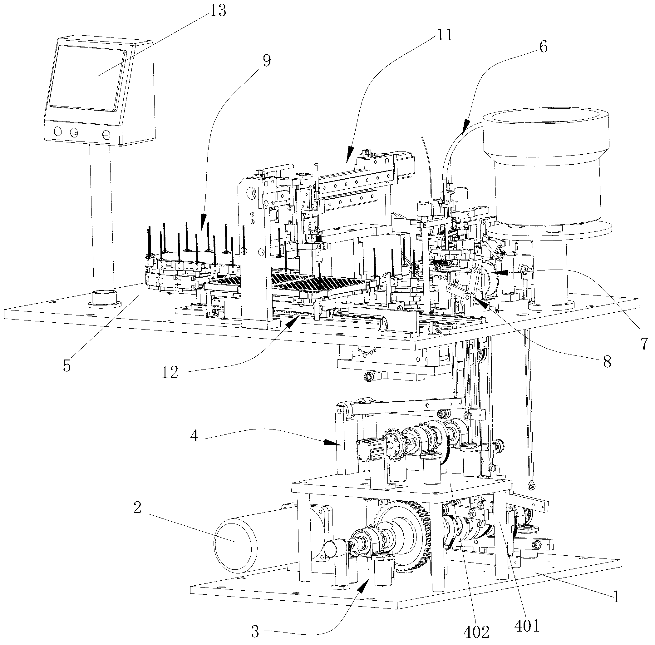
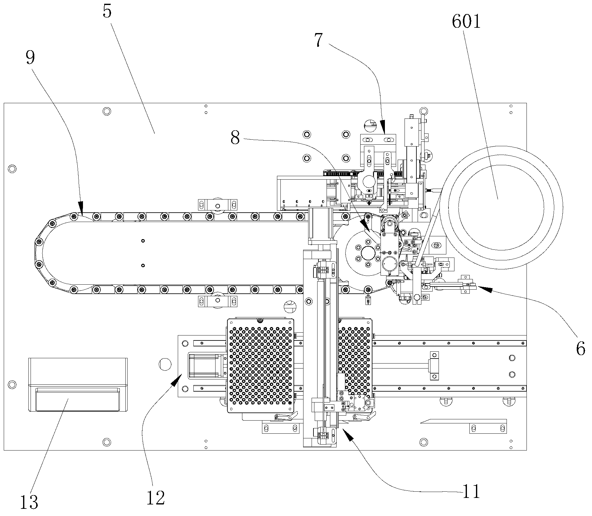
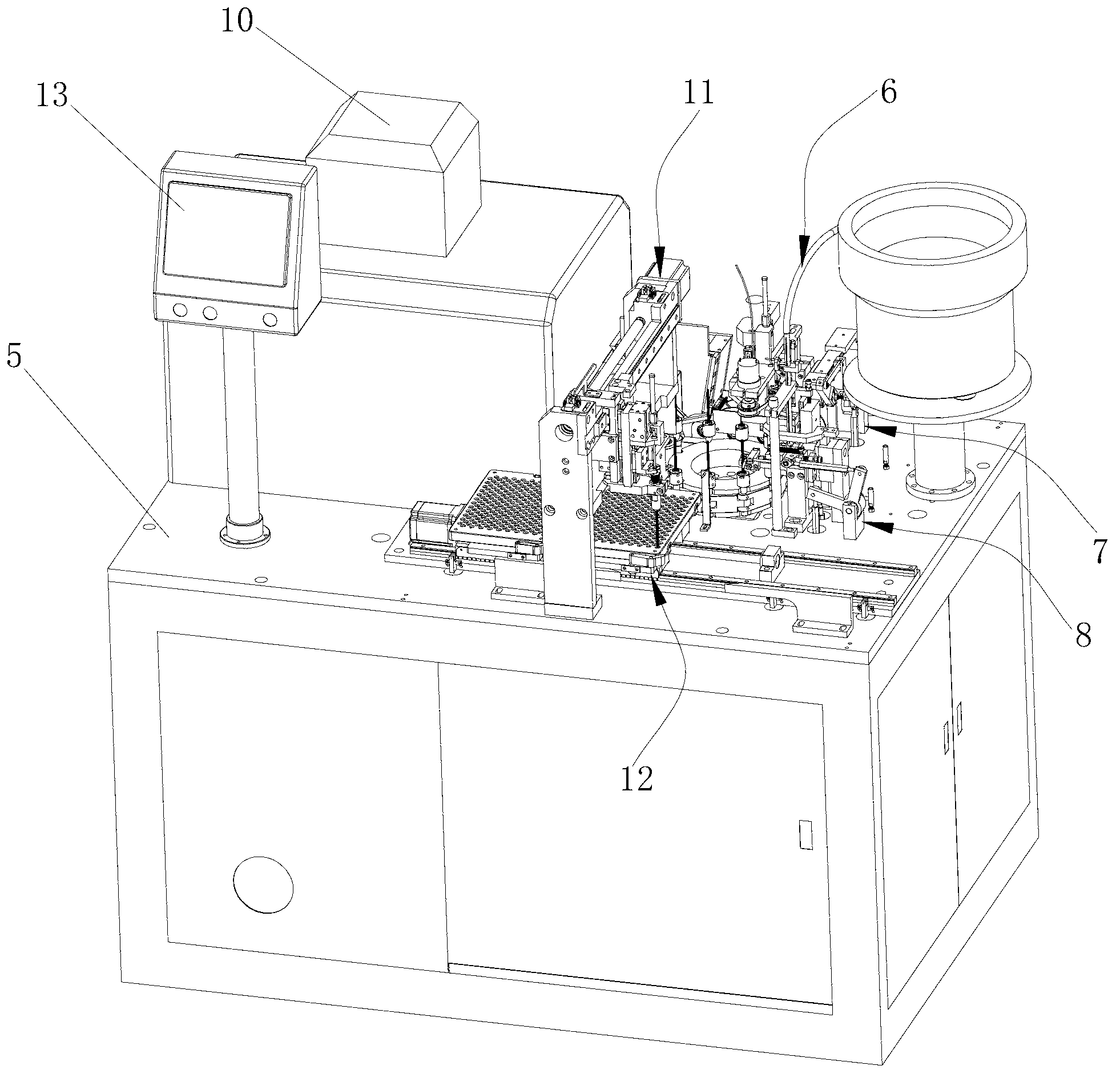
[0028] refer to figure 1 , figure 2 , image 3 , Figure 4 , Figure 5 , Figure 6 , Figure 7 , Figure 8 , Figure 9 , Figure 10 , Figure 11 , Figure 12 , Figure 13 , Figure 14 , Figure 15 , Figure 16 , Figure 17 , Figure 18 , providing a micro motor rotor automatic assembly machine, including a first base plate 1, a workbench 5 installed above the first base plate 1, and a driving motor 2, a main transmission mechanism 3, a secondary Transmission mechanism 4, the driving motor 2 is connected with the main transmission mechanism 3, the auxiliary transmission mechanism 4 is installed above the main transmission mechanism 3, the workbench 5 is equipped with a magnetic ring assembly mechanism 6, and the rotor shaft is dispensing and rotating The displacement mechani...


PUM


Abstract

The invention discloses an automatic assembling machine for a micro motor rotor. The automatic assembling machine comprises a first base plate, a worktable which is arranged above the first base plate, a driving motor, a main transmission mechanism, an auxiliary transmission mechanism, a magnet ring assembling mechanism, a rotor shaft glue dispensing, rotating and moving mechanism, a rotor shaft assembling mechanism and a jig linkage mechanism, wherein the driving motor, the main transmission mechanism and the auxiliary transmission mechanism are arranged in the first base plate, the driving motor is connected with the main transmission mechanism in a driving way and the auxiliary transmission mechanism is arranged above the main transmission mechanism; and the magnet ring assembling mechanism, the rotor shaft glue dispensing, rotating and moving mechanism, the rotor shaft assembling mechanism and the jig linkage mechanism are arranged on the worktable, one end of the jig linkage mechanism is arranged below the magnet ring assembling mechanism and the rotor shaft assembling mechanism, the magnet ring assembling mechanism is connected with the auxiliary transmission mechanism in a driving way, and the rotor shaft glue dispensing, rotating and moving mechanism, the rotor shaft assembling mechanism and the jig linkage mechanism are respectively connected with the main transmission mechanism in a driving way. By using the automatic assembling machine, the magnet rings and the rotor shaft of the micro motor rotor can be automatically assembled into the rotor. The automatic assembling machine for the micro motor rotor has the advantages that the automation level is high, the labor cost is low, the assembling efficiency is high, the product quantification rate can be effectively improved, and the like.

Description

technical field [0001] The invention relates to a machine for assembling products, more specifically, relates to an automatic assembly machine for automatically assembling parts of a rotor of a micro motor into a rotor of a micro motor. Background technique [0002] The micro motor rotor is composed of the rotor shaft and more than one magnetic ring. The traditional assembled micro motor rotor is manually assembled, which has the disadvantages of low assembly efficiency, unstable product quality, low product qualification rate, and high labor cost. To meet the demand for standardization, mechanization and large-scale production of micro motors. Contents of the invention [0003] The purpose of the present invention is to overcome the above-mentioned defects in the prior art, and provide a micro motor rotor automatic assembly machine with high degree of mechanization, high assembly efficiency, stable product quality, effective improvement of product qualification rate, and ...

Claims


Application Information

Patent Timeline
IPC IPC(8): H02K15/02
Inventor 袁振海潘其圣
Owner DONGGUAN YI CHENG AUTOMATIC EQUIP
Learn More