
Heat treating apparatus

A technology of heat treatment device and treatment chamber, which is applied in coating, gaseous chemical plating, metal material coating process, etc., can solve the problem of wafer temperature uniformity deterioration, wafer temperature uniformity deterioration, temperature uniformity damage, etc. problems, to achieve the effect of improving heating efficiency and accurate control

Active Publication Date: 2015-04-08
TOKYO ELECTRON LTD +1
View PDF5 Cites 0 Cited by
  • Summary
  • Abstract
  • Description
  • Claims
  • Application Information

AI Technical Summary

Problems solved by technology

[0005] However, if the above-mentioned heat treatment device based on the cold wall method is used to arrange a plurality of heating seats with small heat capacity for high-frequency induction heating, due to the temperature difference between the heating seat and its surroundings (inner wall of the reaction tube, etc.), the heating seat surface and The temperature uniformity between the heating seats is destroyed, not only the temperature uniformity between the wafers placed on each heating seat is deteriorated, but also the in-plane temperature uniformity of the wafer is also deteriorated. The essence of this cold wall method is problem also becomes apparent

Method used


Image

  • Heat treating apparatus
  • Heat treating apparatus
  • Heat treating apparatus

Examples


Embodiment Construction

[0059] Hereinafter, preferred embodiments of the present invention will be described in detail with reference to the drawings. In addition, in this specification and drawings, the same code|symbol is attached|subjected to the structural unit which has substantially the same functional structure, and repeated description is abbreviate|omitted.

[0060] (Example of configuration of heat treatment equipment)

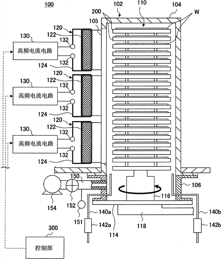
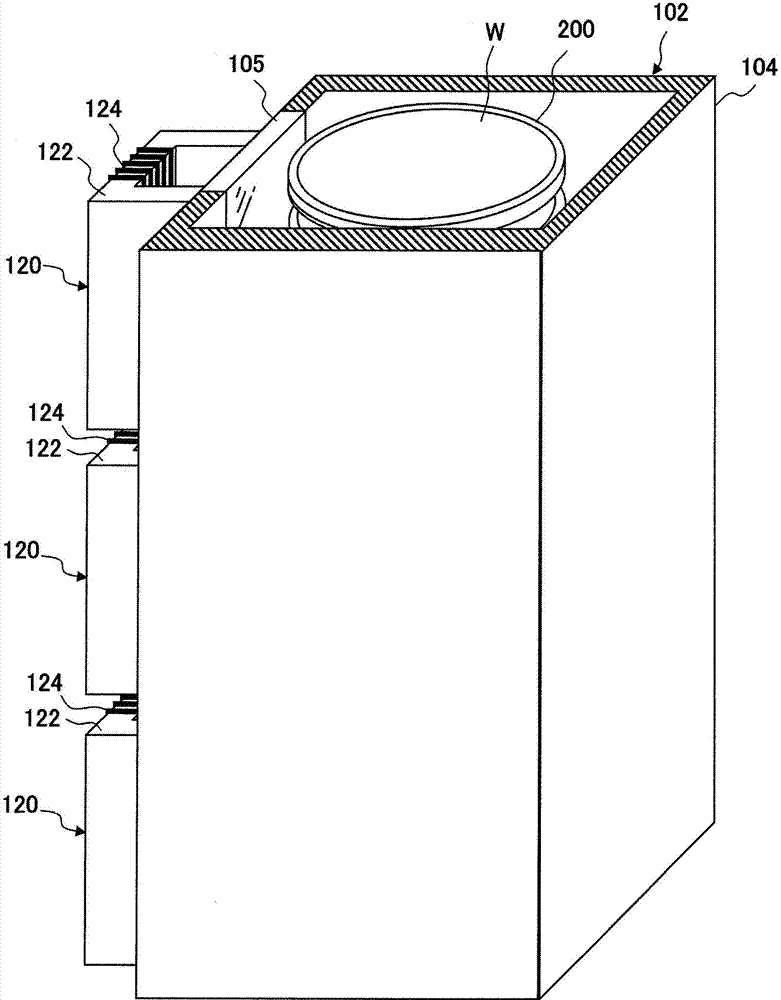
[0061] First, a heat treatment apparatus according to an embodiment of the present invention will be described. Here, with reference to the accompanying drawings, a batch-type vertical heat treatment device (hereinafter referred to simply as a "heat treatment device") capable of heat-treating multiple pieces of a semiconductor wafer (hereinafter referred to as a "wafer") as a substrate to be processed will be described. ) as an example to illustrate. figure 1 is a cross-sectional view showing a configuration example of a heat treatment apparatus, figure 2 It is a perspe...


PUM


Abstract

The purpose of the invention is to accurately control the in-plane temperature of susceptors by controlling the penetration of magnetic flux entering from rim portions of the susceptors. A heat treating apparatus is provided with: susceptors (200) which are conductive members with a loading surface on which a substrate is to be carried, each susceptor being divided into a rim portion (210) and an interior portion (220) surrounded by same, said interior portion comprising a thick plate-like heat generating body, and said rim portion formed by layering thin plate-like heat generating bodies, which are thinner than the interior portion, in a manner electrically insulated from each other; and electromagnets (120) which, from the lateral side of the susceptors, form alternating current magnetic fields parallel to the loading surfaces. The heat treating apparatus performs temperature control by causing the ratio between heat generation at the rim portion of each susceptor and heat generation at the interior portion to change by using two frequencies of high frequency current applied to the induction coil (124) wounded around the electromagnets to control the induction current generated at each thin film-like heat generating body and control penetration of magnetic flux up to the interior portions.

Description

technical field [0001] The present invention relates to a heat treatment apparatus for performing predetermined heat treatment on substrates such as semiconductor wafers and glass substrates. Background technique [0002] When manufacturing a semiconductor integrated circuit, various heat treatments such as a silicon film or a silicon oxide film and the like, and various heat treatments such as oxidation treatment are performed on the surface of the substrate. When performing these heat treatments, a so-called batch-type heat treatment apparatus capable of arranging a plurality of semiconductor wafers (hereinafter, simply referred to as "wafers") and performing heat treatment at one time is often used. [0003] As a batch type heat treatment apparatus, an electric furnace system (hot wall system) in which an electric furnace is used to heat a reaction tube accommodating a plurality of wafers is mainly used. However, in the electric furnace system, since the heat capacity of...

Claims


Application Information

Patent Timeline
Patent Type & Authority Patents(China)
IPC IPC(8): H01L21/22C23C16/46H01L21/205H01L21/31H01L21/324
CPCH01L21/67109H01L21/67303H01L21/324
Inventor 米永富广河野有美子内田直喜尾崎一博
Owner TOKYO ELECTRON LTD
Learn More