
Method for preparing thermal barrier coating on surface of engine turbine blade

A technology of turbine blade and thermal barrier coating, which is applied in the field of preparing thermal barrier coating on the surface of engine turbine blades, can solve problems such as melting deformation and high power, and achieve the effect of avoiding overheating damage and uniform surface temperature distribution

Active Publication Date: 2022-04-01
BEIHANG UNIV +2
View PDF0 Cites 0 Cited by
  • Summary
  • Abstract
  • Description
  • Claims
  • Application Information

AI Technical Summary

Problems solved by technology

[0006] Based on this, it is necessary to provide a method for preparing thermal barrier coatings on the surface of engine turbine blades in view of the high power of PS-PVD.

Method used


Image

  • Method for preparing thermal barrier coating on surface of engine turbine blade
  • Method for preparing thermal barrier coating on surface of engine turbine blade
  • Method for preparing thermal barrier coating on surface of engine turbine blade

Examples


Embodiment

[0088] Embodiment: prepare uniform YSZ coating on a kind of duplex aeroengine guide vane 10

[0089] 1. Pretreatment of blade 10

[0090] Use a magnetic polishing machine to polish the blade 10 on which the metal bonding layer has been deposited. The magnetic polishing speed is 2000 rpm, the polishing time is 10 minutes, and the surface roughness of the blade body 12 is tested to Ra figure 2 .

[0091] 2. Install shielding tooling

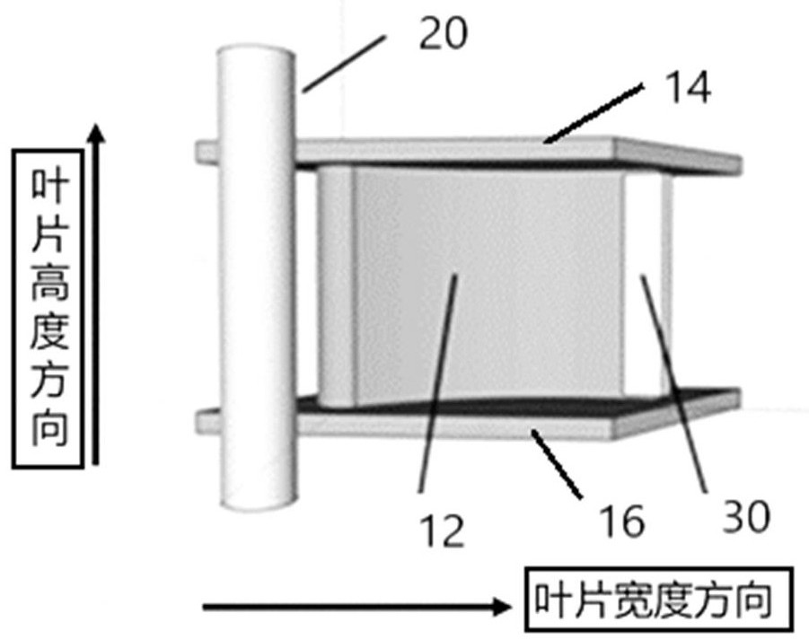
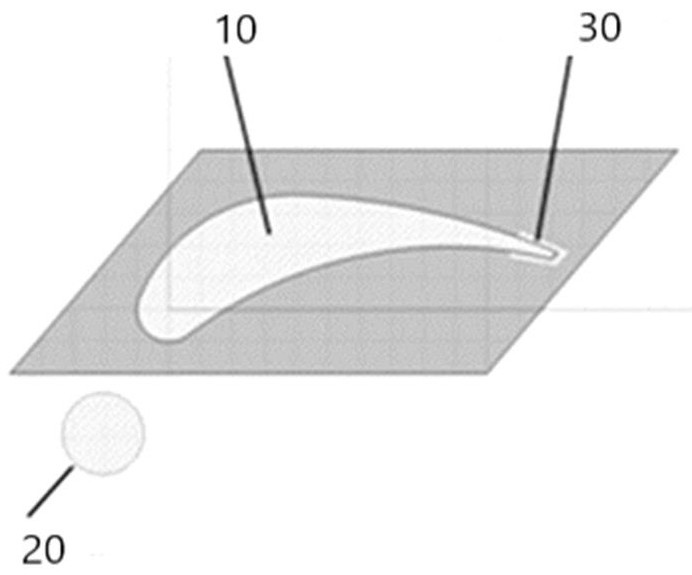
[0092] Install shielding tooling around the blade 10, use a cylindrical shield rod to protect the edge position of the blade 10, and use a follow-up shield 30 to protect the trailing edge of the blade 10. The size of the cylindrical shielding rod is: 10 mm in diameter, 200 mm in length; the size of the follow-up shielding sheet 30 is: 3 mm in thickness, and the length covers the trailing edge of the blade 10 . according to Figure 1A , Figure 1B The leading edge and the trailing edge of the blade 10 are protected in a middle way.

[0093] 3. ...


PUM

PropertyMeasurementUnit
diameteraaaaaaaaaa
thicknessaaaaaaaaaa

Abstract

The invention discloses a method for preparing a thermal barrier coating on the surface of an engine turbine blade, which comprises the following steps: arranging a wrap-around shield at a certain distance from the surface of the turbine blade, so that the plasma jet first bypasses the surface of the turbine blade when spraying on the surface of the turbine blade The above-mentioned wrapping shield reaches the surface of the turbine blade again; the surface of the turbine blade is sprayed using the PS-PVD process.

Description

technical field [0001] The invention relates to the technical field of coating preparation, in particular to a method for preparing a thermal barrier coating on the surface of an engine turbine blade. Background technique [0002] Thermal barrier coatings have become one of the indispensable key technologies for the protection of high-performance aero-engine hot-end components. Typically, thermal barrier coatings include a bonding layer (Bond Coat, BC) and a ceramic layer (Top Coat, TC). The bonding layer is located between the top ceramic layer and the substrate in the thermal barrier coating, and is used to relieve the internal stress caused by the difference in thermal expansion coefficient between the superalloy substrate and the ceramic layer, while protecting the substrate from oxidation. The ceramic layer mainly plays a role of heat insulation and reduces the surface temperature of the metal layer. [0003] Atmospheric plasma spraying (APS) and electron beam physica...

Claims


Application Information

Patent Timeline
Patent Type & Authority Patents(China)
IPC IPC(8): C23C14/04C23C14/22C23C4/11C23C4/134
CPCC23C14/042C23C14/22C23C4/134C23C4/11
Inventor 郭洪波石佳何雯婷魏亮亮刘巧沐陈基东张书
Owner BEIHANG UNIV
Learn More