

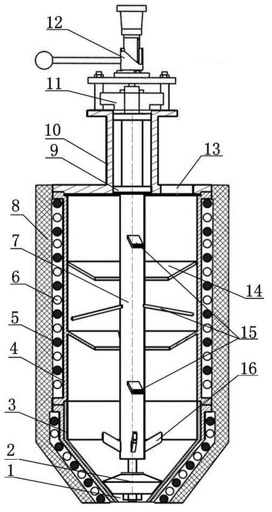
Continuous preparation device for composite stirred semi-solid slurry
A semi-solid slurry and preparation device technology, which is applied in the direction of stirring devices, lighting and heating equipment, furnace components, etc., to achieve the effects of similar grain size, good cooling effect, and wide application prospects
- Summary
- Abstract
- Description
- Claims
- Application Information
AI Technical Summary
Problems solved by technology
Method used
Image

Examples
example 1
[0021] (1) The liquidus temperature of the ZL104 aluminum alloy used in the test is 610°C. The alloy is melted in a crucible resistance furnace. When the temperature of the alloy reaches about 720°C, the dried hexachloroethane is pressed into the melt The lower part of the alloy body (the addition amount is 0.5% of the total weight of the alloy liquid) is gently shaken to carry out the degassing and slag removal refining treatment of the alloy melt, and finally the temperature of the alloy melt is lowered to 630°C for heat preservation.
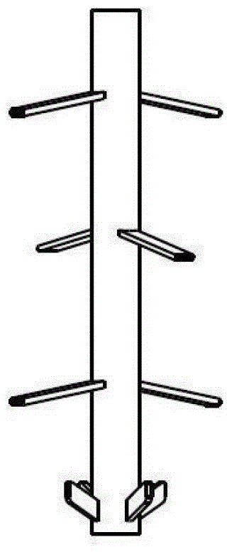
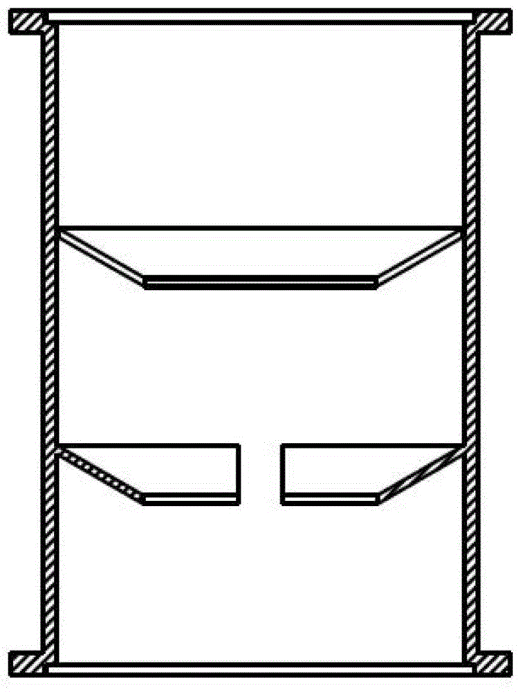
[0022] (2) Set the temperature of the stirring chamber of the device of the present invention to 580°C, turn on the speed regulating motor to make the rotating speed of the stirring screw rod 400rad / min, close the graphite plug, block the discharge port, and after each parameter reaches the set value, turn the previous The melted alloy liquid is poured into the mixing chamber of the device of the present invention through the feed port, and th...
example 2
[0024] (1) The liquidus temperature of the 7075 aluminum alloy used in the test is 640°C. Put the aluminum alloy ingot into a crucible resistance furnace with a preheating temperature of 400°C. After the temperature of the alloy liquid reaches 720°C, it is refined. Press the dried hexachloroethane into the lower part of the melt (the amount added is 0.5% of the total weight of the alloy liquid), and shake it gently to degas the alloy melt, remove slag and refine it, and finally melt the alloy Body temperature drops to 660°C for heat preservation.
[0025] (2) Set the temperature of the stirring chamber of the device of the present invention to 610°C, turn on the speed-regulating motor to make the stirring screw rotate at 600 rad / min, rotate the discharge handle, lift the graphite plug and fix it at a certain position to ensure that the slurry flows out slowly. After each parameter reaches the set value, the alloy liquid smelted in the previous step is continuously poured into ...
PUM
 Abstract
Description
Claims
Application Information